- Catalogs
- PROMAX ELECTRONICA
- EC-696 Analogue Communications training system
EC-696 Analogue Communications training system

EC-696 Analogue Communications training system
- Signal Inputs: Includes CO1 and CO2 inputs from a generator with a maximum level of ±3 V and a bandwidth of DC to 20 kHz. Microphone inputs (MIC1 and MIC2) have a sensitivity of 6 mVpp, adjustable, with an input impedance of 20 kΩ at 1 kHz.
- Modulators: Features AM, FM, PWM, and FDM/FM modulators with carrier frequencies of 100 kHz or 300 kHz, selectable. Modulation indices and bandwidths vary per modulator type.
- Emitters: Includes bifilar cable, coaxial cable, fibre optic, infrared, and 27 MHz emitters, each with specific output levels and emission bands.
- Receivers: Supports bifilar cable, coaxial cable, fibre optics, infrared, and radio receivers, each with specific receiving bands and efficiencies.
- Demodulators: Includes AM, FM, PWM, and FDM/FM demodulators with specific bandwidths and carrier frequencies.
- Output Specifications: Provides earphone outputs with independent volume control and oscilloscope outputs with specified levels.
Catalog excerpts
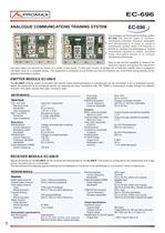
EC-696 has several types of emitters,transmission channels, receivers, modulators and demodulators, in order to shape a transmission system easily. For instance, it permits to compare the advantages of several transmission systems to others, including those fibre-optics based, or to analyse interference phenomena.Easy to use and the capability to measure theelectrical signals throughout the equipmenthas been taken into account by means of a series of test points. To this end, circuitry is located into a desk-like cabinet, with a transparentfold-down cover for a complete access. The equipment is composed of one Emitter set and one Receiver set, to be linked during training, by theselected transmission method. EC-696/E emitting system is provided with several inputs where generators or microphones can be connected. A set of sequential controlsallows the equipment to be configured quickly, by selecting the input, modulation (AM, FM, PWM) or transmission modes through five differentchannels: twin cable, coaxial, fibre-optic, infrared or radio. EMITER MODULESignal inputs CO1 and CO2Input from a generatorMaximum level 3 VBandwidthDC to 20 kHzInput impedance 20 k (1 kHz)MIC1 and MIC2Microphone inputsSensitivity6 mVpp, adjustableInput impedance Emitters Bifilar cable transmitterOutput through operational amplifierMaximum levelѱ 3 VCoaxial cable transmitterOutput through operational amplifierMaximum level 3 VFibre optic transmitterEmissionBy LED PhotodetectorEmitting band650 nm (red colour)Infrared ray transmitterEmissionBy LED PhotodetectorEmitting band950 nm27 MHz EmitterOutput level0 dBmModulation index50 %Antenna 1.5 m cable Monopole The 20 k (1 kHz) Modulators AM ModulatorVoltage-controlled gain amplifierCarrier frequency100 kHzModulation index0 to 100%Bandwidth DC to 20 kHzFM ModulatorVoltage-controlled oscillatorCarrier frequency100 kHzFrequency deviationѱ 50 kHzBandwidthDC to 20 kHzPulse Modulator (PWM)Carrier frequency100 kHz Duty cycle 40 to 70%BandwidthDC to 20 kHzFDM/FM ModulatorVoltage-controlled oscillatorCarrier frequency300 kHz or 100 kHz, selectableChannel bandwidthDC to 20 kHz > Signals processed by the EC-696/E can be received and demodulated by the EC-696/R . This system is configured by four pushbuttons and a logiccontrol, the same way as in the emitter. The demodulated and separate signals received can be displayed on the screen of an oscilloscope or monitored by means of earphones. The analogue communications training system RECEIVER MODULEReceivers Bifilar cable receiverDirect, without processingCoaxial cable receiverDirect, without processingFibre optics receiverType (PIN) type Photodiode Receiving band400 to 1100 nm (90% efficiency)Infrared receiverTypePIN type photodiodeReceiving band800 to 1000 nm (50% efficiency)Radio receiverPeak detectorReceiving band27 MHzAntenna1.5 m Cable Output specifications Earphone outputOutput stageAB Class Volume controlIndependent for left and right channelsOutput power200 mW over 32 Demodulator specifications (3 Vpp in C)Oscilloscope S1 and S2 outputs Output level AM DemodulatorFast detectorBandwidthDC to 20 kHz (bifilar and coaxial)300 Hz to 20 kHz (fibre, infrared and radio) FM DemodulatorDPLL typeCarrier frequency100 kHzBandwidthDC to 20 kHz (bifilar and coaxial)Pulse demodulator (PWM)Integrator typeCarrier frequency100 kHzBandwidthDC to 20 kHz (bifilar and coaxial)300 Hz to 20 kHz (fibre, infrared and radio)FDM/FM DemodulatorDPLL typeCarrier frequency300 or 100 kHz selectableMultiplex bandwidthDC to 20 kHz (bifilar and coaxial)300 Hz to 20 kHz (fibre, infrared and radio) 400 m Vpp (3 Vpp in A) >
Open the catalog to page 1All PROMAX ELECTRONICA catalogs and technical brochures
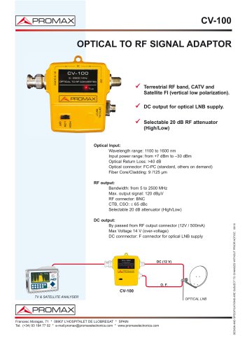 CV-100
1 Page
 PROMAX-12
2 Pages
 CV-223
1 Page
 HD RANGER Lite
2 Pages
 PROLITE-30B
1 Page
 HD RANGER 3
8 Pages
 HD RANGER +
12 Pages
 HD RANGER 2
19 Pages
 IL-185 Lux meter
1 Page
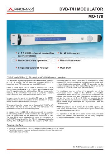
 MO-160 DVB-T Modulator
2 Pages
 GV-198 Video generator
2 Pages
 RM-204 PkWatch
14 Pages


- Power supply unit
- DC power supply
- AC/DC power supply
- Liquids analyzer
- Infrared imager
- Monitoring camera system
- Benchtop analyser
- Portable analyzer
- Signal amplifying integrated circuit
- Thermographic camera
- Digital tester
- Tabletop power supply
- Water analyzer
- Multimeter
- Variable-output power supply
- Digital multimeter
- Power amplifying integrated circuit
- Portable multimeter
- Power quality analyzer