PS00xxA
1 /11Pages

PS00xxA
1 /11Pages
Catalog excerpts
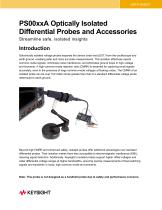
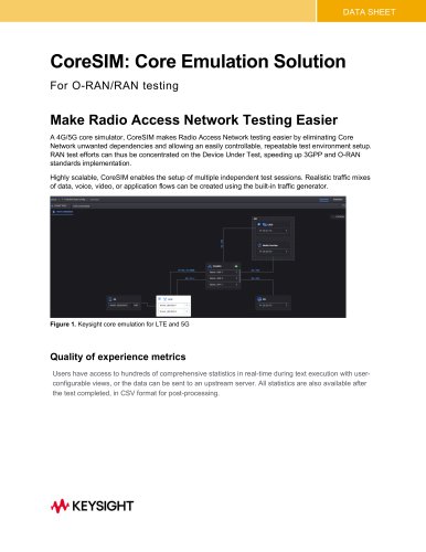
DATA SHEET PS00xxA Optically Isolated Differential Probes and Accessories Streamline safe, isolated insights Introduction Galvanically isolated voltage probes separate the device under test (DUT) from the oscilloscope and earth ground, enabling safer and more accurate measurements. This isolation effectively rejects common-mode signals, minimizes noise interference, and eliminates ground loops in high-voltage environments. A high common-mode rejection ratio (CMRR) is essential for capturing small signals accurately, even in the presence of large common-mode voltages at floating nodes. The CMRR of an isolated probe can be over 100 million times greater than that of a standard differential voltage probe referenced to earth ground. Beyond high CMRR and enhanced safety, isolated probes offer additional advantages over standard differential probes. Their isolation makes them less susceptible to electromagnetic interference (EMI), reducing signal distortion. Additionally, Keysight’s isolated probes support higher offset voltages and wider differential voltage ranges at higher bandwidths, ensuring precise measurements of fast-switching signals and transients in noisy, high-common-mode environments. Note: This probe is not designed as a handheld probe due to safety and performance concerns.
Open the catalog to page 1
Isolated probes offer significant benefits across multiple industries and applications. Most commonly used in power electronic full-bridge and half-bridge architectures, they enhance efficiency and performance testing of fast-switching devices such as wide bandgap GaN and SiC semiconductors. With support for high-voltage differential measurements up to ±2,500 V and the ability to reject common-mode signals up to ±60,000 V, isolated probes play a critical role in applications like automotive electric vehicle (EV) testing and photovoltaic solar power conversion. Other key applications include:...
Open the catalog to page 2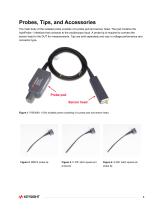
Probes, Tips, and Accessories The main body of the isolated probe consists of a probe pod and sensor head. The pod contains the AutoProbe 1 interface that connects to the oscilloscope input. A probe tip is required to connect the sensor head to the DUT for measurements. Tips are sold separately and vary in voltage performance and connector type. Probe pod Sensor head Figure 1. PS0008A 1 GHz isolated probe consisting of a probe pod and sensor head. Figure 2. MMCX probe tip Figure 3. 0.100” pitch square pin Figure 4. 0.200” pitch square pin
Open the catalog to page 3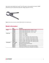
Each probe comes standard with a bipod. Use of the bipod is recommended for maximum CMRR performance and for measurement setups with voltages larger than 30 Vrms. Probes PS0004A Optically Isolated Differential Probe, 350 MHz, 2-meter PS0006A Optically Isolated Differential Probe, 700 MHz, 2-meter PS0008A Optically Isolated Differential Probe, 1 GHz, 2-meter Probe Tips PS0017A Probe Tip, ± 10 V, MMCX PS0022A Probe Tip, ± 10 V, 100 mil pitch, 0.025” square pin socket PS0023A Probe Tip, ± 100 V, 100 mil pitch, 0.025” square pin socket PS0025A Probe Tip, ± 500 V, 100 mil pitch, 0.025” square pin...
Open the catalog to page 4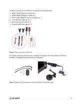
The Basic Connectivity Kit (PS0010A) includes the following accessories: • DP0021-60002 Solder-in Y-lead tip qty. 1 • DP0021-60001 Socketed Y-lead tip qty. 1 • PP0013-60001 MMCX to square pin adapter qty. 1 • 1400-3652 Micro SMD clip qty. 2 • Microcircuit hook test clips qty. 2 • Channel identification rings qty. 12 Figure 6. Basic connectivity kit (PS0010A) For sturdier positioning and placement, an adapter for Keysight’s 3D probe positioner (N2787A) is available. The adapter requires assembly once delivered. Figure 7. Adapter for 3D probe positioner disassembled (left) and assembled
Open the catalog to page 5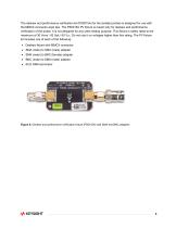
The deskew and performance verification kit (PS0015A) for the isolated probes is designed for use with the MMCX connector-style tips. The PS0015A PV fixture is meant only for deskew and performance verification of the probe. It is not designed for any other testing purpose. This fixture is safely rated to the maximum of 30 Vrms / 42 Vpk / 60 VDC. Do not use it on voltages higher than this rating. The PV fixture kit includes one of each of the following: • Deskew fixture with MMCX connector • SMA (male) to SMA (male) adapter • SMA (male) to BNC (female) adapter • BNC (male) to SMA (male) adapter...
Open the catalog to page 6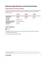
The electrical ratings below are for probe pods and sensor heads without a probe tip. Each isolated probe requires the use of a probe tip, and therefore, the lower electrical rating of the two is applicable when used in combination. Bandwidth (-3 dB)1 Probe interface Cable length Cable type Overvoltage and measurement category per IEC -61010-0312 Safety certification Output drive Optical fiber bundle Non-CAT (mains isolated) These probes are Class 1 laser systems under “Normal Use” conditions and comply with IEC 608251:2014 standards for laser systems. View the User Guide for additional certifications....
Open the catalog to page 7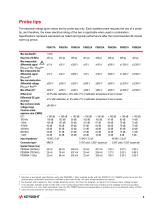
The electrical ratings given below are for probe tips only. Each isolated probe requires the use of a probe tip, and therefore, the lower electrical rating of the two is applicable when used in combination. Specifications represent warranted (as noted) and typical performance after the recommended 30-minute warm-up period. Max measurable yjy differential signal Max measurable AC differential signal Max non-destructive differential voltage Offset error Differential DC gain accuracy Max common-mode voltage range Common mode rejection ratio (CMRR) ±250 V ±250 V ±250 V ±250 V ±500 V ±500 V ±2,500...
Open the catalog to page 8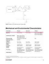
Mechanical and Environmental Characteristics Characteristic Probe pod Sensor head Probe tip Dimensions 124 x 36 x 53 mm 99 x 30 x 25 mm 232 x 35 x 29 mm (MMCX) MMCX: 2,432 mm ±30 mm 100 mil: 2,438 mm ±30 mm 200 mil: 2,457 mm ±30 mm 375 g (probe pod + sensor head) Combined probe + tip lengthApproximate weight Oscilloscope interface Temperature Dew Point) derated linearly 2 (rated for indoor use only) 0°C to +55°C -40°C to +70°C Dew Point) derated linearly Dew Point) derated linearly 7 Qualified for 140 hours of continuous use. 8 Normally only non-conductive pollution occurs. Occasionally, however,...
Open the catalog to page 9All Prisma Telecom Testing S.r.l catalogs and technical brochures
 F8800B PROPSIM F64
10 Pages
 F8800A PROPSIM F64
8 Pages
 Selecting a Signal Generator
32 Pages
 N5511A
31 Pages
 Logic Analyzer Probing Solutions
75 Pages
 Signal Analyzers X-Series
21 Pages
 Signal Analysis Solutions
26 Pages
 DP001xA Series
10 Pages
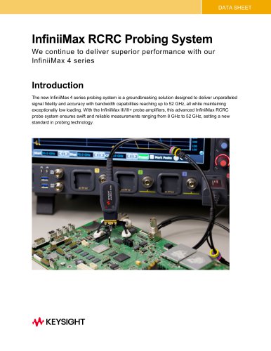 InfiniiMax RCRC Probing System
17 Pages
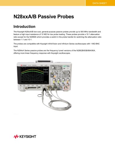 N28xxA/B Passive Probes
7 Pages
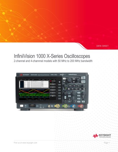 InfiniiVision 1000 X-Series
23 Pages
 RuSIM O-DU Testing Solution
6 Pages
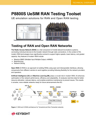 P8800S UeSIM RAN Testing Toolset
15 Pages