N5511A
1 /31Pages
N5511A
1 /31Pages
Catalog excerpts

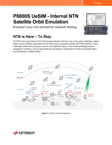
N5511A Phase Noise Test System (PNTS) With over 50 years of low phase noise, RF design, and measurement experience, Keysight solutions provide excellent measurement integrity, repeatability, and accuracy.
Open the catalog to page 1
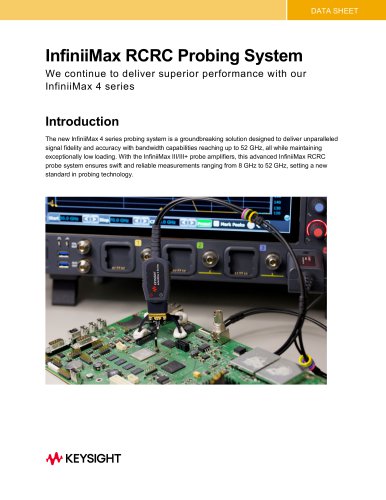
N5511A PNTS Overview The Keysight Technologies, Inc. N5511A Phase Noise Test System (PNTS) is a replacement for the “gold-standard” Keysight E5500 phase noise measurement system. PNTS is the foundation of test systems that can measure phase noise down to kT (-177 dBm/Hz at room temperature). This thermal phase noise floor is the theoretical limit for any measurement. Therefore, the PNTS can measure at the limits of physics. Phase noise is unwanted phase modulation noise that emerges from nearly all radio frequency (RF) and microwave devices including oscillators, mixers, frequency dividers, frequency...
Open the catalog to page 3
• RF input frequency range: 50 kHz to 40 GHz using internal phase detectors • Use of external phase detectors allows measurements of millimeter-wave singals to beyond 100 GHz • Wide carrier offset range capability, from 0.01 Hz to 160 MHz internally (more than ten decades) • Absolute and residual phase noise using the phase detector (quadrature) method in both singlechannel and two-channel configurations. Two-channels enables use of cross-spectral averaging (cross-correlation) for improving sensitivity down to “kT,” the thermal phase noise floor (-177 dBm/Hz) • Measurement of one-port devices...
Open the catalog to page 4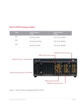
Figure 1: The PXI modules comprising the N5511A PNTS Find us at www.keysight.com Page 5
Open the catalog to page 5
Keysight N5511A PNTS Theory of Operation Phase Detector Technique The “phase detector with PLL and reference source” technique is the most general-purpose and sensitive measurement approach available for measuring the single sideband (SSB) phase noise characteristic of oscillators (absolute phase noise). This technique removes the carrier and demodulates the phase noise sidebands of the device-under-test (DUT) oscillator. The resulting baseband signal is then digitized and converted into the frequency domain using a Fast-Fourier Transform (FFT) by dedicated baseband analysis hardware. By using...
Open the catalog to page 6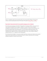
Figure 2. Simplified single-channel absolute phase noise measurement diagram showing three sources of total measured phase noise at the output of the system: ∅(ݒ)հݒŰݒְݒ , բȅ(ݒ)հݒӰݒưݒ and ǰݑհݑͰݒİݒ Dual-channel measurements with cross-spectral averaging (cross-correlation) One of the main advantages of the N5511A Phase Noise Test System (PNTS) is the dual-channel cross-spectral averaging (cross-correlation) capability. In a dual-channel cross-correlation configuration, the phase noise of the RF or microwave reference no longer limits the effective noise floor of the absolute phase noise measurement....
Open the catalog to page 7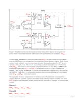
Figure 3. Simplified dual-channel absolute phase noise measurement diagram showing only one source of total measured phase noise at the output of the system after cross-correlation: ∅(ݒ)հݒŰݒְݒ A power splitter splits the DUT signal (with phase noise բȅ(ݒ)հݒŰݒְݒ ) into two channels, and each signal goes into the RF port of two separate (and thus independent) phase detector modules. Each module contains double-balanced mixers used as phase detectors. Because the post-splitter DUT signal is identical in both paths, both channels will receive totally correlated (identical) phase noise from the DUT...
Open the catalog to page 8
We can think of the cross-correlation (also known by the shorthand “Xcorr”) process as comparing the output phase noise from each channel and suppressing the phase noise that is different (uncorrelated) in each channel and keeping the phase noise that is the same (correlated). After suppressing the terms that are different and keeping the terms that are the same, we are left with only the phase noise of the DUT: Xcorr(ݑͰݑͰݑ۰ݒİݒɰݟ , ϰݑͰݑͰݑ۰ݒİݒɰݟ ) = Тȅ(ݒ)հݒŰݒְݒ With cross-correlation, the PNTS can suppress any noise that doesnբt originate from the DUT and achieve an ultimate sensitivity approaching...
Open the catalog to page 9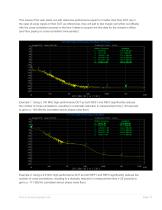
This means if the user starts out with reference performance equal to or better than their DUT (as in the case of using copies of their DUT as references), they will add to test margin (at further out offsets) with the cross-correlation process in the time it takes to acquire the first data for the closest-in offset (and thus paying no cross-correlation time-penalty). Example 1: Using a 100 MHz high-performance DUT as both REF1 and REF2 significantly reduces the number of cross-correlations -resulting in a dramatic reduction in measurement time (~40 seconds to get to a -184 dBc/Hz correlated...
Open the catalog to page 10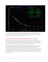
Amplitude . -60.63 dBc/Hz -90.77 dBc/Hz -116.09 dBc/Hz -141.92 dBc/Hz -156.87 dBc/Hz . -163.9 dBc/Hz -163.68 dBc/Hz -166.22 dBc/Hz .Marker Frequency ____ Example 3: Using a 10 MHz high-performance DUT as both REF1 and REF2 significantly reduces the number of cross-correlations -resulting in a dramatic reduction in measurement time (~20 minutes to get to a -60 dBc/Hz correlated device phase noise at a .01 Hz offset) Theoretically, kT (thermal noise power density) is a physical floor limiting the achievable phase noise performance of any DUT (as well as the measurement system) and is defined by...
Open the catalog to page 11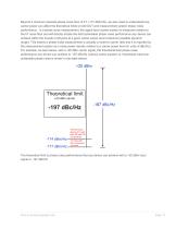
Beyond a minimum absolute phase noise floor of kT (-177 dBm/Hz), we also need to understand how carrier power can affect the theoretical limits to both DUT and measurement system phase noise performance. In a phase noise measurement, the signal level (carrier power) is measured relative to the kT noise floor and will directly dictate the best achievable phase noise performance any device can achieve within the bounds of physics at a given carrier power level (maximum possible dynamic range). This means a phase noise measurement is actually a noise-to-carrier ratio and it is reported by the measurement...
Open the catalog to page 12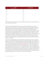
The theoretical (kT) limit to phase noise (ǰݓ(۰ݒ)) performance that any device can achieve with various input carrier power levels (Pcarrier) Now that we have established the theoretical maximum phase noise performance any DUT or measurement system can achieve, letǢs explore practical limits to measurement system noise floor (also known as sensitivity and residual noise floor). The single-channel configuration of the N5511A PNTS is limited by the 1/f noise and noise figure of the phase detector and baseband signal processing blocks as we saw earlier represented by added noise ݑհݑͰݒİݒ . In the...
Open the catalog to page 13All Prisma Telecom Testing S.r.l catalogs and technical brochures
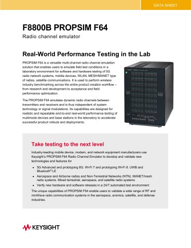 F8800B PROPSIM F64
10 Pages
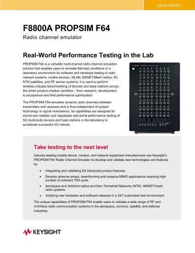 F8800A PROPSIM F64
8 Pages
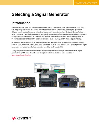 Selecting a Signal Generator
32 Pages
 Logic Analyzer Probing Solutions
75 Pages
 Signal Analyzers X-Series
21 Pages
 Signal Analysis Solutions
26 Pages
 DP001xA Series
10 Pages
 InfiniiMax RCRC Probing System
17 Pages
 PS00xxA
11 Pages
 N28xxA/B Passive Probes
7 Pages
 InfiniiVision 1000 X-Series
23 Pages
 RuSIM O-DU Testing Solution
6 Pages
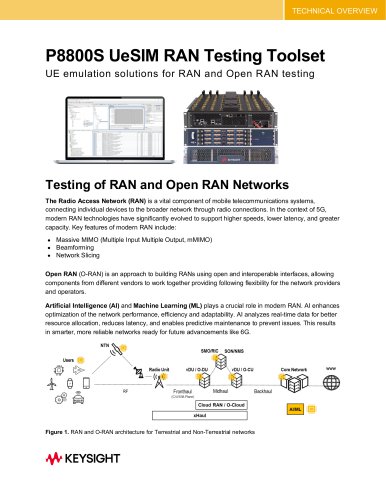 P8800S UeSIM RAN Testing Toolset
15 Pages