- Catalogs
- Prisma Telecom Testing S.r.l
- Infiniium Oscilloscope Probes and Accessories

Infiniium Oscilloscope Probes and Accessories
Infiniium Oscilloscope Probes and Accessories
Catalog excerpts
Infiniium Oscilloscope Probes and Accessories
Open the catalog to page 1
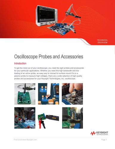
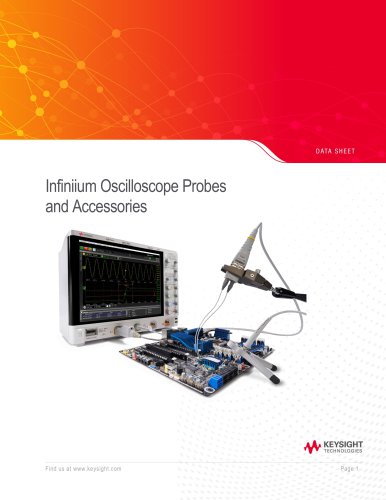
To get the most out of your Keysight Technologies, Inc. Infiniium oscilloscope, you need the right probes and accessories for your particular applications. Whether you need the high bandwidth and low loading of an active probe, an easy way to connect to surface mount ICs, or a passive probe to measure high voltages, there’s a wide selection of high-quality probes and accessories for your Infiniium oscilloscope.
Open the catalog to page 2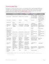
To assist you in selecting the proper probe for your application use our probe compatibility table below to find the probes that are recommended for use with your Infiniium scope. To best help you in probe selection, check out our Oscilloscope Probe Selection Guide. For the most up-to-date compatibility between the probes and scopes, check out the Probe Resource Center. 1. The 1147B, N2790A and N2893A are not compatible with 80000, 90000 and 90008 Series scopes. 2. UXR with AutoProbe III interface (1 and 1.85 mm models) requires N2852A interface adapter to accommodate probes with AutoProbe II...
Open the catalog to page 3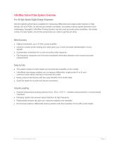
Get the highest performance available for measuring differential and single-ended signals on high-density ICs and PCBs. As devices get smaller and faster, accurately probing signals becomes more challenging. Keysight’s InfiniiMax Probing System has the most accurate probe amplifiers, the widest variety of probe heads, and all the accessories you need to get the job done. • Highest bandwidth, up to 30 GHz probe amplifier • Industry’s lowest probe loading and noise gives you a more accurate representation of your signals • S-parameter corrections for a more accurate probe response • Flat frequency...
Open the catalog to page 4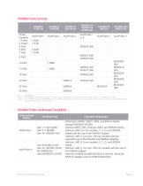
Find us at www.keysight.com Page 5
Open the catalog to page 5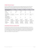
Not only do InfiniiMax probes have the best accuracy and highest performance, they also offer a wide range of features to make the InfiniiMax probing system the easiest probing system to use. Not all features are found across all generations. Check out the chart and explanations of the features below. An ideal probe would simply provide an exact replica of the signal being probed. But, in the real world, the probe becomes part of the circuit under test because the probe introduces loading to the circuit. The probe impedance, thus probe loading changes with frequency. To get the most accurate...
Open the catalog to page 6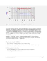
Figure 1. Input impedance profile of two common probe architectures: RC and RCRC The InfiniiMax probes can be divided into two main categories: RC and RCRC architecture. As pictured above, an RC input impedance architecture has the lowest loading and least signal distortion across the widest frequency range. At lower frequencies, you can see that the input impedance is driven by input R of the probe. It then intersects the capacitance of the probe. The RCRC architecture is best when higher bandwidth is necessary, or for signals that have low source impedance. You can see here that at higher frequencies...
Open the catalog to page 7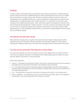
InfiniiMode In many of today’s high-speed serial bus standards, the accurate measurement of single-ended and common-mode components of a differential signal is often compromised by having to rely on multiple probe channels and a scope’s internal math functions, but these methods are prone to errors and cumbersome to use. InfiniiMode allows you to measure differential, single-ended and common-mode characteristics of a differential signal with a signal connection. You will need to connect four inputs consisting of two differential signal inputs: +lead, -lead and two ground connections to make the...
Open the catalog to page 8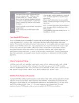
When an InfiniiMax probe is connected to a scope channel and the proper probe head is selected, the scope calculates a DSP correction filter that includes the probe head, probe amplifier, and scope channel. This provides the maximum measurement accuracy for the complete probe and scope channel system. Some InfiniiMax probes store unique S parameters in on board memory for the scope to read out when the probe amp is connected to the scope. Unique S-parameters, as opposed to nominal, means each individual probe amp contains its own frequency response data to further flatten the magnitude and phase...
Open the catalog to page 9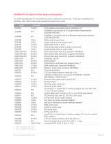
The following table lists all compatible RC probe heads and accessories. These are compatible with InfiniiMax Gen I/II/RC/Ultra probe amplifiers except where noted. Find us at www.keysight.com Page 10
Open the catalog to page 10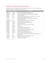
The following table lists compatible RCRC probe heads and accessories. These are compatible with InfiniiMax Gen III/III+ probeamplifiers except where noted. Find us at www.keysight.com Page 11
Open the catalog to page 11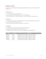
The latest series of InfiniiMax probes for high speed digital designers. They are the most accurate and easiest to use. • Lowest noise to see your signal more clearly • More breadth with 5 models ranging from 10 to 25 GHz of bandwidth • Highest input impedance in midband frequencies, crucial for probing high impedance modes • Highest accuracy across the widest frequency range to see the truest representation of your signal • Lowest loading for least impact to your circuit • Boost test margins with the least signal distortion from your probe • Easily probe small devices with the super flexible...
Open the catalog to page 12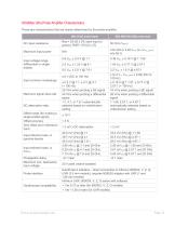
These are characteristics that are mainly determined by the probe amplifier. Find us at www.keysight.com Page 13
Open the catalog to page 13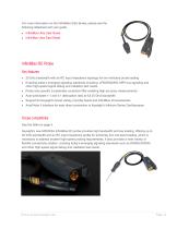
For more information on the InfiniiMax Ultra Series, please see the following datasheet and user guide. • InfiniiMax Ultra User Guide • InfiniiMax Ultra Data Sheet • 25 GHz bandwidth with an RC input impedance topology for low mid-band probe loading • Enabling today’s emerging signaling standards including: LPDDR/DDR5, MIPI bus signaling and other high-speed signal debug and validation test needs • Probe amp specific S parameter correction filter enabling high accuracy measurements • Auto-switchable 1:1 and 4:1 attenuation ratio at full 25 GHz bandwidth • Support for Keysight’s broad variety...
Open the catalog to page 14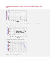
Characteristics performance plots: MX0023A 25 GHz probe amp with MX0100A micro probe head Frequency response of an ideal 25 GHz brickwall filter (red) and the typical DSP corrected probe response filtered by the brickwall filter (blue). Time domain step responses for the two responses CMRR for the 1:1 (red) and 4:1 (blue) mode.
Open the catalog to page 15All Prisma Telecom Testing S.r.l catalogs and technical brochures
 F8800B PROPSIM F64
10 Pages
 F8800A PROPSIM F64
8 Pages
 Selecting a Signal Generator
32 Pages
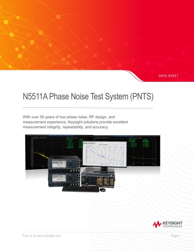 N5511A
31 Pages
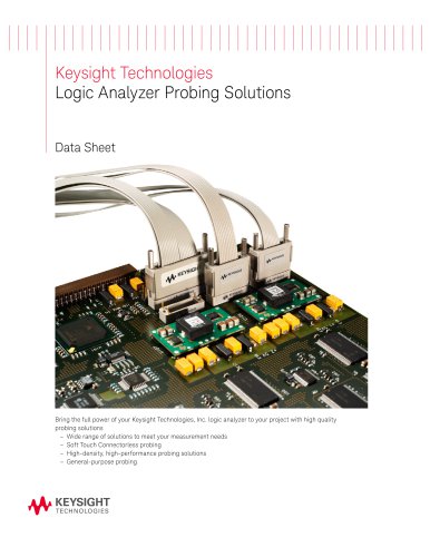 Logic Analyzer Probing Solutions
75 Pages
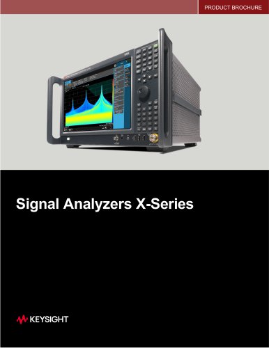 Signal Analyzers X-Series
21 Pages
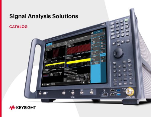 Signal Analysis Solutions
26 Pages
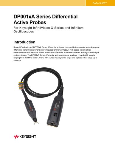 DP001xA Series
10 Pages
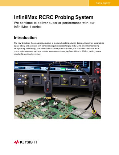 InfiniiMax RCRC Probing System
17 Pages
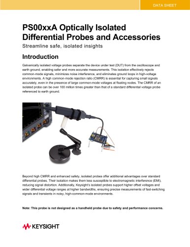 PS00xxA
11 Pages
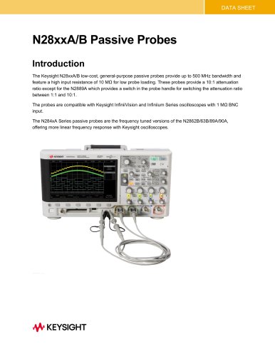 N28xxA/B Passive Probes
7 Pages
 InfiniiVision 1000 X-Series
23 Pages
 RuSIM O-DU Testing Solution
6 Pages
 P8800S UeSIM RAN Testing Toolset
15 Pages