TNRP51
1 /29Pages

TNRP51
1 /29Pages
Catalog excerpts

Pulse Radar Liquid Level Transmitter Pulse Radar Liquid Level Transmitter Prisma Instruments Expertise & Industrial Solutions
Open the catalog to page 1
PRISMA Instruments & Gauge Bourdon France 1. Measurement Principle • Principle The extremely narrow microwave pulse emitted by the antenna on radar level instrument can travel at the speed of light and part of its energy, which is reflected off the surface of target medium, is received by the very same antenna. The time lapse between pulse emission and reception by the antenna is proportional to the distance between the surface of target medium and the reference point on antenna. However, due to the fact that the electromagnetic wave is transmitted at extremely high speed, which leads to the...
Open the catalog to page 3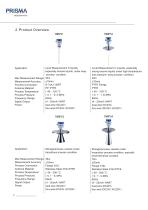
PRISMA Tnstru me n ts & Gauge Bourdon France Max Measurement Range: Measurement Accuracy: Process Connection: Antenna Material: Process Temperature: Process Pressure: Frequency Range: Signal Output: Power Application: Max Measurement Range Measurement Accuracy: Process Connection: Antenna Material: Process Temperature: Process Pressure: Frequency Range: Signal Output: Power Level Measurement in liquids, especially erosive liquids, under easy process condition 30m ±10mm G1^A,1^NPT PP/PTFE (-40-120)oC (-0. 1-0. 3) MPa 6GHz (4-20)mA/HART dual-wire (DC24V) four-wire (DC24V/AC220V) Level Measurement...
Open the catalog to page 4
Pulse Radar Liquid Level Transmitter 6.3GHz 3. Mounting Requirements Basic Requirements There is a certain existing beam angle while the antenna transmitting microwave pulses. There should beno barriers between the lower edge of antenna and surface of measuredmedium. Therefore it is highly recommended to avoid facilities inside vessels, such asladders, limit switches, heating spirals, struts and etc, during the mounting process. “False echo learning” must be carried out during the installation in this case.Furthermore, microwave beams must NOT intersect the filling streams. Be cautions duringthe...
Open the catalog to page 5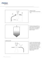
1.Reference Plane 2.Center of Vessel or Symmetrical Axis The best mounting position for a conical vessel with flat top is the center of its top, as the effective measurement can reach the bottom of vessel. Damp-proof In order to avoid dampness under outdoor or humid indoor conditions or for those instruments mounted on cooling/heating vessels, seal rings used on cables should be screwed tight, plus the cable must be bended downward outside cable entry, indicated on the diagram below
Open the catalog to page 6
Pulse Radar Liquid Level Transmitter 6.3GHz Socket Horn Antenna The transducer end must at least protrude 10mm out of socket. Antenna Extension You are advused to use antenna extension if the antenna is shorter than socket. Rod Antenna The working part of antenna ,ie. the cone-shaped body of antenna must be fully exposed from the socekt. In orderto meet the application requirement of various sockets, different radar level instrumentsof various sockets, different radar level instruments of variable length are available for customers to choose from(see Chapter 6 Dimensional Drawings).
Open the catalog to page 7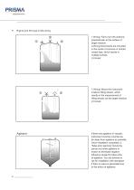
Rights and Wrongs in Mounting 2 1 1.Wrong: Fail to turn the antenna prependicular to the surface of target medium. 2.Wrong:Instruments are mounted in the center of concave or arched vassel tops, which results in multiple echoes. 3.Correct 1.Wrong: Mount the instrument in/above filling stream, which results in the measurement of filling stream not the target medium. 2.Correct: If there are agitators in vessels, instrument must be mounted as far away from agitators as possible. Once installation completed, a "false echo learning" should be carried out while agitators in motion to eliminate negative...
Open the catalog to page 8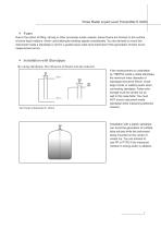
Pulse Radar Liquid Level Transmitter 6.3GHz Foam Due to the action of filling, stirring or other processes inside vessels, dense foams are formed on the surface of some liquid medium, which could attenuate emitting signals considerably. You are advised to mount the instrument inside a standpipe or opt for a guided wave radar level instrument if the generation of foam incurs measurement errors. Installation with Standpipe By using standpipe, the influence of foams can be reduced. Vent hole of diameter 5-10mm If the measurement is undertaken by TNRP5X inside a metal standpipe, the minimum inner...
Open the catalog to page 9
4 Electrical Connection Power Supply 20mA/HART(2-Wire) Power supply and current signal are carried by the same two-wire connection cable. See the Technical Specifications of this guide for detailed requirement on power supply. A safety barrier should be placed between power supply and instrument for intrinsically safe version. 20mA/HART(4-wire) Power supply and current signal are carried by two 2-wire connection cables respectively. See the Technical Specifications of this guide for detailed requirement on power supply. Earth-connected current output can be used for standard version of level...
Open the catalog to page 10
Pulse Radar Liquid Level Transmitter 6.3GHz 4-wire/2-chamber 220V AC Power Supply, 4…20mA Signal Output(electronic unit D) Wiring Diagram Wiring Diagram 4-wire 24V DC Power Supply, 4…20mA Signal Output(electronic unit C) Wiring Diagram dual-wire 24V DC Power Supply, 4…20mA Signal Output(electronic unit E) Note: 24V DC switch on 4 4…20mA switch on
Open the catalog to page 11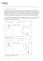
Explosion Proof Connection This product is an intrinsic safety explosion proof version (Exia C T6) with aluminium housing and plasticencapsulated internal structure aimed to prevent sparks resulted from transducer and circuit malfunction from leaking out. It is applicable for the non-contact continuous level measurement of flammable medium under the level of explosion proof inferior to Exia c T6.You are required to use FBS-2 series (intrinsic safety explosion proof: [Exia] C voltage of power supply: 24V DCK5% short-circuit current: 135mA operating current: 4...20mA) of safety barriers, which...
Open the catalog to page 12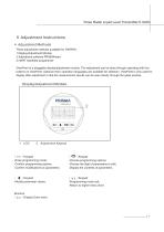
Pulse Radar Liquid Level Transmitter 6.3GHz 5 Adjustment Instructions Adjustment Methods Three adjustment methods available for TNRP5X: 1.Display/Adjustment Module 2.Adjustment software PRISMAware 3.HART handheld programmer ViewPoint is a pluggable display/adjustment module. The adjustment can be done through operating with four buttons on ViewPoint. Optional menu operation languages are available for selection. ViewPoint is only used for display after adjustment in that the measurement results can be seen clearly through the glass window. Display/Adjustment Module Adjustment Keypad [ O K ]Keypad...
Open the catalog to page 13All Prisma Instruments catalogs and technical brochures
 DUS-TT-CE
4 Pages
 DUS-TT-FC
5 Pages
 MODEL : APG
2 Pages
 Prisma série PI700
2 Pages
 DUS-TT-F Gold
3 Pages
 RTD Complet
14 Pages
 SYS-4U4000-5S01
2 Pages
 SYS-4U4000-4A03
2 Pages
 Additel 761
5 Pages
 DUS-TT-PC
4 Pages
 Temperature Gauges
16 Pages
 Hygiene Gauges HYG
2 Pages
 ADT-680
2 Pages
 DPG-B
DPG-B2 Pages
 SFBSPG
2 Pages
 PMH700 & PMH1000
2 Pages

- Flowmeter
- Panel PC
- Industrial panel PC
- Volume flow monitor
- Liquid flow monitor
- Fanless panel PC
- LCD panel PC
- Intel® Core™ panel PC
- Pressure transmitter
- Pressure gauge
- Waterproof flow meter
- Analog pressure transmitter
- Digital temperature control
- Stainless steel flow monitor
- Pressure switch
- Industrial flow monitor
- Analog pressure gauge
- Precision flow meter
- 15" panel PC
- Industrial thermometer