Prince Valves
1 /90Pages

Prince Valves
1 /90Pages
Catalog excerpts
PRINCE MANUFACTURING CORPORATION • NORTH SIOUX CITY, SOUTH DAKOTA 57049 URL: www.princehyd.com • E-MAIL: [email protected] O.E.M. CUSTOMER SERVICE: (605) 235-1220 • FAX (712) 233-2181 DISTRIBUTOR CUSTOMER SERVICE: PHONE (605) 235-1220 • FAX (712) 233-2181
Open the catalog to page 2
Directional Control Valves SECTIONAL BODY STANDARD FEATURES PRINCE MANUFACTURING CORPORATION • NORTH SIOUX CITY, SOUTH DAKOTA 57049 URL: www.princehyd.com • E-MAIL: [email protected] O.E.M. CUSTOMER SERVICE: (605) 235-1220 • FAX (712) 233-2181 DISTRIBUTOR CUSTOMER SERVICE: PHONE (605) 2
Open the catalog to page 3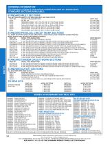
ORDERING INFORMATION: The following is a listing of valve sections available from stock on a standard basis. STANDARD SECTIONS AVAILABLE: STANDARD INLET SECTIONS ALL SECTIONS HAVE BOTH TOP AND SIDE INLET AND TANK PORTS PART NO. RELIEF TYPE AND SETTING 20I2A NO RELIEF 20I2C SHIM ADJUSTABLE 1351-1750 PSI, SET AT 1750 PSI @ 10 GPM 20I2D SHIM ADJUSTABLE 1751-2200 PSI, SET AT 2200 PSI @ 10 GPM 20I2E SHIM ADJUSTABLE 2201-3000 PSI, SET AT 2500 PSI @ 10 GPM 20I2G ADJUSTABLE 1351-1750 PSI, SET AT 1750 PSI @ 10 GPM 20I2H ADJUSTABLE 1750-2200 PSI, SET AT 2200 PSI @ 10 GPM 20I2J ADJUSTABLE 2201-3000 PSI,...
Open the catalog to page 4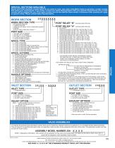
SPECIAL SECTIONS AVAILABLE: Valves other than standard models listed can be made to order. Use order code Matrix below to generate a model number that meets your requirements. If you prefer, contact your Sales Representative with your specific requirements and a model number will be assigned for you. This model number can then be used for future orders. A minimum order quantity will apply to special valves. Please consult Sales Representative. WORK SECTION TYPE PORT RELIEF “B” (LEAVE BLANK FOR 20L) PORT RELIEF “A” (LEAVE BLANK FOR 20L) P-STANDARD PARALLEL T-TANDEM CENTER L-PARALLEL WITH BUILT...
Open the catalog to page 5
CROSS SECTION OF 20P1BA1DA PARALLEL WORK SECTION SPOOLS AND SPOOL ATTACHMENTS OPTION NDETENT SPOOL-OUT W/ SPRING CENTER SPOOL OPTION 'A' - 3 WAY 3 POSITION FOR USE WITH SINGLE ACTING CYLINDERS OR NON-REVERSIBLE MOTORS. THE 'B' WORK PORT IS BLOCKED IN NEUTRAL. OPTION ASPRING CENTER TO NEUTRAL SPOOL OPTION 'B' - 4 WAY 3 POSITION FOR USE WITH DOUBLE ACTING CYLINDERS OR REVERSIBLE MOTORS. THE WORK PORTS ARE BLOCKED IN NEUTRAL. OPTION B3 POSITION DETENT SPOOL OPTION 'C' - 4 WAY 3 POSITION FREE FLOW MOTOR SPOOL. THE WORK PORTS ARE OPEN TO TANK IN NEUTRAL, ALLOWING A MOTOR TO COAST OR A CYLINDER TO...
Open the catalog to page 6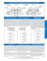
CROSS SECTION OF TANDEM WORK SECTION AND LOCK SECTION THE LOCK SECTION BODY HAS AN "L" ON THE LEFT SIDE OF THE "B" WORK PORT SHOWN WITH MICRO-SWITCH OPTION J A WORK PORT B WORK PORT THE CASTING NUMBER "C-638" IS ON THE RIGHT SIDE OF WORK SECTION BODY THE CASTING NUMBER "C-637" IS ON THE RIGHT SIDE OF WORK SECTION BODY LOCK SECTION TANDEM SECTION MODEL 20P PARALLEL CIRCUIT MODEL 20T TANDEM CIRCUITS Parallel circuit construction is the most common. When any one of the spools in a valve bank is shifted it blocks off the open center passage. The oil then flows into the parallel circuit core making...
Open the catalog to page 7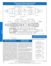
SERIES CIRCUIT SERIES 20 WORK SECTIONS CROSS SECTION OF SERIES SECTION ARROW INDICATES DIRECTION OF OIL FLOW & POINTS TOWARDS OUTLET SECTION DIRECTION OF FLOW TOWARDS OUTLET SECTION ‘A’ WORK PORT O-RING GROOVES SHIM ADJUSTABLE RELIEF SHOWN ADJUSTABLE RELIEF SHOWN VALVES HANDLE OPTION 7 SHOWN HERE CLOSED CENTER APPLICATIONS For solenoid operation with series sections and a 20U utility section, there needs to be a Series 20 tandem section with pilot passageways between the series section and the utility section. In the valve assembly shown below, the first and fourth sections are parallel. The...
Open the catalog to page 8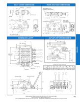
INLET COVER DIMENSIONS WORK SECTIONS DIMENSIONS PART NUMBER WILL BE STAMPED IN THIS LOCATION PART PART NUMBER BE BE NUMBER WILL WILL STAMPED IN THIS PART NUMBER LOCATION PART NUMBER WILL BE WILL BE STAMPED IN THIS LOCATION STAMPED IN THIS LOCATION STAMPED IN THIS LOCATION TOP OUTLET TOP TOP OUTLET TOP INLETINLET TOP OUTLET TOP TOP TOP INLET INLET OUTLET OUTLET TOP 2.69 2.69 2.69 2.69 SYSTEM RELIEF INLETINLET INLET INLET A WORK PORT 1.44 1.44 A WORK 2.88 1.44 1.44 B WORK A WORK PORTPORT 2.88 B WORK PORTPORT A WORK PORT 2.88 RELIEF OPTION A WORK PORT A WORK PORT TRAVEL SPOOL B WORKB WORK PORT 2.88...
Open the catalog to page 9
WORK PORT RELIEF CARTRIDGES INLET RELIEF CARTRIDGES OPTION K ANTI-CAVITATION CHECK This option allows oil to be drawn from the tank core into the work port if there is a vacuum on the work port. This vacuum would be caused by a overrunning motor or cylinder. The check will be open whenever the pressure in the tank core is higher than that in the work port. OPTIONS B, C, D, AND E, SHIM ADJUSTABLE PORT RELIEF A port relief can be installed to limit the pressure at the work port to less than the system pressure. Also, it can be installed to provide spike pressure protection when the spool is in...
Open the catalog to page 10
SERIES 20 MID-INLET SECTION 20IM* X X X X XXXXX 20IM* X X X - - XXXX Mid-Inlet Port Mid-Inlet Port FLOW OPTION FLOW OPTION C -C - COMBINED FLOW COMBINED FLOW S -S - SPLIT FLOW SPLIT FLOW LAST FOUR DIGITS LAST FOUR DIGITS SPECIFY A NONSPECIFY A NONSTANDARD RELIEF STANDARD RELIEF PRESSURE IN PSI. PRESSURE IN PSI. LEAVE BLANK FOR LEAVE BLANK FOR STANDARD SETTING. STANDARD SETTING. PORT SIZE PORT SIZE Mid-Inlet Relief Cartridge/Plug Mid-Inlet Relief Cartridge/Plug MID-INLET RELIEF OPTIONS: MID-INLET RELIEF OPTIONS: Install pipe plug in this location Install pipe plug in this location for for Flow...
Open the catalog to page 11
SERIES 20 FLOW CONTROL INLET SECTION 20IF15 Digits Specify A Non-Standard Relief Pressure in PSI. Leave blank for standard setting. Solenoid Option: (Omit for Flow Opt. ‘M’) 12 D – 12 VDC Deutsch (DT04-2P) MANUAL FLOW CONTROL CARTRIDGE Flow Control Option: M – Manual Control P – Electro-Proportional Pilot Operated Relief Adjustable From 2000-3500 PSI. Standard Relief Setting: 2500 PSI @ 10 GPM This inlet incorporates a manually operated pressure compensated flow control. With the flow control knob turned fully in (clockwise), all of the inlet flow is diverted to the tank core. By turning the...
Open the catalog to page 12All Prince catalogs and technical brochures
 THE MAGNUM LINE 3000 PSI
4 Pages
 Directional Control Valves
4 Pages
 Prince Pumps&Motors
25 Pages
 Prince cylinders,valves,pumps&motors
145 Pages
 Prince cylinder&accessories
26 Pages
 PRINCE PTO HYDRAULIC PUMPS
6 Pages
 general catalog
75 Pages
 Pumps and motors catalog
25 Pages
 cylinders brochure
30 Pages
 cylinders, valves catalog
134 Pages


Archived catalogs
 CMM SERIES GEROTOR MOTOR
3 Pages
 PRINCE HAND PUMP
1 Page
 THE FORTRESS LINE
1 Page


- Lumibird manual valve
- Lumibird control valve
- Lumibird regulating valve
- Lumibird flap valve
- Lumibird check valve
- Lumibird lever valve
- ISO valve
- Directional control valve
- Double-acting cylinder
- Hydraulic pump
- Hydraulic cylinder
- Lumibird oil valve
- Hydraulic directional control valve
- Lumibird flow control valve
- Piston cylinder
- Hydraulic piston pump
- Relief valve
- Spool hydraulic directional control valve