1. Catalogs
  2. Prince
  3. general catalog

general catalog

general catalog
1 / 75 PagesView full catalog

general catalog

Product catalog summary
Overview: The document is a comprehensive technical catalog from Prince Manufacturing Corporation, detailing hydraulic valves and components. It includes specifications, ordering information, and standard features for various valve models.
Model Descriptions: The catalog lists several models of directional control valves, such as Series 20, RD5100, and RD5200, each described with flow capacity and features like solenoid operation and load sensing capabilities.
Standard Features: Common features across models include work sections, power beyond capability, reversible handles, load checks, and chrome-plated spools. Valves are designed for parallel or tandem circuit foot mounting with a maximum operating pressure of 3500 psi.
Specifications: Detailed specifications for each valve include pressure ratings, weight, nominal flow ratings, and maximum operating temperatures. Fluid cleanliness according to ISO standards is emphasized for optimal performance.
Ordering Information: A comprehensive list of available valve sections and kits is provided, including part numbers and descriptions for easy ordering.
Port Relief Cartridges: Various port relief cartridges are available with adjustable pressure settings from 500 to 3000 psi, with ordering codes and specifications outlined.
Inlet and Outlet Sections: Standard inlet and outlet sections are described, specifying configurations for open, closed, and power beyond outlets.
Work Sections: Details on different work section types, spool types, and actions are provided, along with handle options and a matrix for generating model numbers.
Assembly and Customization: Valves can be ordered as separate sections or complete assemblies, with custom valves available for specific needs.
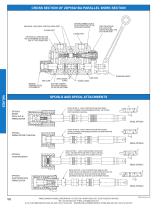
Spool Options: Four spool options (A, B, C, D) are outlined for different applications, specifying flow and blocking characteristics in neutral positions.
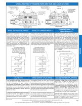
Circuit Configurations: Parallel and tandem circuit constructions are described, with a combination of both usable in a valve bank.
Load Check and Center Systems: Each work port has a load check to prevent cylinder fall and back-flow, with specific configurations for open or closed center systems.
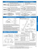
Relief Options: Various relief options, including shim adjustable and anti-cavitation checks, help manage pressure and protect against spikes.
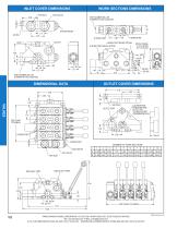
Dimensional Data: Detailed dimensions for inlet, work sections, and outlet covers are provided.
Outlet Section Options: Options include standard open center, closed center, and power beyond configurations.
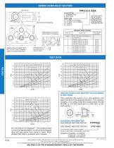
Mid-Inlet Section: Allows for a second pump inlet mid-stream in the stack valve, providing combined flow for downstream sections.
Contact Information: Prince Manufacturing Corporation's contact details are provided for customer service and further inquiries.
Pressure Drop and Flow Characteristics: Pressure drop from the work port to the tank and flow characteristics relative to spool position are outlined, with graphs illustrating flow and pressure drop relationships.
Compensator Settings: Compensator settings for different flow rates are specified, with options for various PSI settings.
Joystick Handles: Special joystick handles for Series 20 stack valves allow operation of two adjacent sections with a single handle.
Solenoid Operated Work Sections: Solenoid operated sections allow for remote electrical or manual control, with detailed configurations and options.
Valve Assembly and Specifications: The Model SV sectional body directional control valve can be ordered as separate sections or as a complete assembly, with specifications including pressure ratings and flow ratings.
Application Notes: Specific instructions are provided for plugging the load sense port and using the appropriate compensator based on flow requirements.
Inlet Configurations: Conversion of a split mid-inlet to a combined mid-inlet is described, along with the installation of a power core blocking plate.
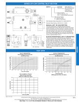
Control Options: Three control options are outlined: Proportional flow control, solenoid-operated unloader cartridge, and manually operated pressure-compensated flow control cartridge.
Solenoid-Operated Work Sections: Operation of Type "-T" and Type "-S" solenoid-operated work sections is detailed.
Specifications: Key specifications include a maximum operating pressure of 3000 psi, a nominal flow rating of 12 GPM, and a maximum operating temperature of 180°F.
Ordering Information: Part numbers and ordering details for various components are provided.
Model RD5000 Series: Describes the RD5000 series of mono-block directional control valves, with specifications on capacity, maximum pressure, and weight.
Valve Features: Monoblock construction, load check on each spool, adjustable from 500 to 1500 PSI, hard chrome plated spool, power beyond and closed center capability, and optional 4 Position Float on 1st spool.
Spool Options: Various spool options are detailed, including 4 Way 3 Position Tandem Center and 4 Way 4 Position Open Center Float Spool.
Pressure Drop and Relief Curves: Pressure drop values and relief curves for different flow rates and configurations are included.
Applications: Open Center and Closed Center Applications are described, with suitable systems and configurations.
Solenoid Operated RD5000 Directional Control Valve: Specifications and functionality for solenoid-operated valves are provided, including installation and pressure build-up valve details.
Model RD4100 Single Spool Monoblock Valve: Specifications and features for the RD4100 model are outlined.
Model LVS Series Loader Valve: Specifications and features for the LVS series loader valve are detailed.
Remote Cable Control: Controllers and control cables for remote cable control are described.
Valve Models: LVT and LVR models are described, with specifications and operational features.
Operational Features: 4-way, 4-position float and regen spool operations for loader boom and bucket functions are detailed.
Additional Components: Seal Kits, Power Beyond Kits, and Relief Cartridges are available for customization and maintenance.
Recommendations: Proper filtration and pressure settings are recommended to maintain optimal performance and longevity of the valves.
Specifications: Maximum design and test pressure, tank port pressure, flow rating, relief valve setting, weight, recommended filtration, and maximum operation temperature are specified.
Standard Features: Economical monoblock construction, load check, hard chrome plated spool, adjustable ball spring relief, and open center to closed center conversion are described.
Open to Closed Center Conversion: Conversion details for open center valves to closed center operation are provided.
Parts Breakdown: Part numbers for various kits and components are listed.
Non-Standard Relief Settings: Relief settings and pressure compensated adjustable flow control valves are described.
Applications: RD-100/RD-1900 valves can be used to control the speed of a hydraulic motor and function as adjustable priority dividers or restrictive type flow controls.
Constant Volume Priority Dividers: RD-400 model specifications and features are detailed.
Adjustable Priority Dividers: RD-500 model specifications and features are outlined.
Proportional Flow Dividers: RD-200 and RD-300 models are described, with specifications and features.
Internally Piloted Sequence Valves: RD-1000S model specifications and features are detailed.
Differential Poppet Style Relief Valves: RV and DRV series specifications and features are outlined.
Special Models and Kits: Special models and field conversion kits for relief valves are mentioned.
DS Double Selector Valve: Specifications and features for the DS Double Selector Valve are provided.
RD-1400 and RD-1600 Pilot-Operated Check Valves: Specifications and features for these models are detailed.
Hydraulic Cylinder Speed and Force: Formulas and charts for calculating cylinder speed and force are provided.
Miscellaneous Hydraulic Information: Recommendations for hydraulic fluid, filtration, and thread sealant are included.
Valve Quick Reference Guide: Comparison of Parker/Gresen models to Prince Manufacturing models is provided.
Contact Information: Prince Manufacturing Corporation's contact details are provided for customer service and further inquiries.
See more

Catalog excerpts

general catalog-1

Prince Manufacturing Corporation North Sioux City, South Dakota

 Open the catalog to page 1
general catalog-2

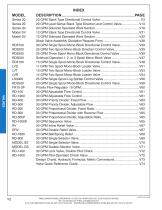
MODEL Series 20 Series 20 Series 20 Model SV Model SV PRINCE MANUFACTURING CORPORATION • P.O. BOX 7000 • NORTH SIOUX CITY, SOUTH DAKOTA 57049-7000 URL: www.princehyd.com • E-MAIL: [email protected] O.E.M. CUSTOMER SERVICE: (605) 235-1220 • FAX (712) 233-2181 DISTRIBUTOR CUSTOMER SERVICE: PHONE (605) 235-1220 • FAX (712) 233-2181

 Open the catalog to page 2
general catalog-3

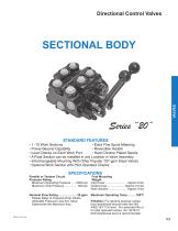
Directional Control Valves SECTIONAL BODY Series “20”” STANDARD FEATURES • 1 -10 Work Sections • Extra Fine Spool Metering • Power Beyond Capability • Reversible Handle • Load Checks on Each Work Port • Hard Chrome Plated Spools • A Float Section can be Installed in any Location in Valve Assembly • Interchangeable Mounting With Other Popular “20” gpm Stack Valves • Optional Work Section with Pilot Operated Checks PRINCE MANUFACTURING CORPORATION • P.O. BOX 7000 • NORTH SIOUX CITY, SOUTH DAKOTA 57049-7000 URL: www.princehyd.com • E-MAIL: [email protected] O.E.M. CUSTOMER SERVICE: (712) 233-2181...

 Open the catalog to page 3
general catalog-4

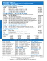
ORDERINg INFORMATION: The following is a listing of valve sections available from stock on a standard basis. STANDARD SECTIONS AVAILABLE: STANDARD INLET SECTIONS ALL SECTIONS HAVE BOTH TOP AND SIDE INLET AND TANk PORTS PART NO. RELIEF TYPE AND SETTINg 20I2A NO RELIEF 20I2C SHIM ADJUSTABLE 1351-1750 PSI, SET AT 1750 PSI @ 10 GPM 20I2D SHIM ADJUSTABLE 1751-2200 PSI, SET AT 2200 PSI @ 10 GPM 20I2E SHIM ADJUSTABLE 2201-3000 PSI, SET AT 2500 PSI @ 10 GPM 20I2G ADJUSTABLE 1351-1750 PSI, SET AT 1750 PSI @ 10 GPM 20I2H ADJUSTABLE 1750-2200 PSI, SET AT 2200 PSI @ 10 GPM 20I2J ADJUSTABLE 2201-3000 PSI,...

 Open the catalog to page 4
general catalog-5

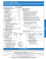
SPECIAL SECTIONS AVAILABLE: Valves other than standard models listed can be made to order. Use order code Matrix below to generate a model number that meets your requirements. If you prefer, contact your Sales Representative with your specific requirements and a model number will be assigned for you. This model number can then be used for future orders. A minimum order quantity will apply to special valves. Please consult Sales Representative. WORk SECTION TYPE PORT RELIEF “B” PORT RELIEF “A” P-STANDARD PARALLEL T-TANDEM CENTER L-PARALLEL WITH BUILT IN PILOT OPERATED CHECKS** A - NO RELIEF B...

 Open the catalog to page 5
general catalog-6

CROSS SECTION OF 20P1BA1DA PARALLEL WORK SECTION INDIVIDUAL LOAD CHECK FOR EACH WORK PORT THE PARALLEL WORK SECTION SIDE OF THE B WORK PORT WORK SECTION BODY STANDARD SPOOL STANDARD HANDLE POWER CORES NOTCHES STAMPED INTO SPOOL PROVIDE EXTRA FINE METERING SPOOLS AND SPOOL ATTACHMENTS SPRING CENTER SPOOL OPTION 'A' - 3 WAY 3 POSITION FOR USE WITH SINGLE ACTING CYLINDERS OR NON-REVERSIBLE MOTORS. THE'B'WORK PORT IS BLOCKED IN NEUTRAL. SPRING CENTER TO NEUTRAL SPOOL OPTION 'B'-4WAY3 POSITION FOR USE WITH DOUBLE ACTING CYLINDERS OR REVERSIBLE MOTORS. THE WORK PORTS ARE SPOOL OPTION 'C- 4 WAY 3 POSITION...

 Open the catalog to page 6
general catalog-7

CROSS SECTION OF TANDEM WORk SECTION AND LOCk SECTION THE LOCK SECTION BODY HAS AN "L" ON THE LEFT SIDE OF THE "B" WORK PORT SHOWN WITH MICRO-SWITCH OPTION J A WORK PORT B WORK PORT THE CASTING NUMBER "C-638" IS ON THE RIGHT SIDE OF WORK SECTION BODY THE CASTING NUMBER "C-637" IS ON THE RIGHT SIDE OF WORK SECTION BODY LOCK SECTION TANDEM SECTION MODEL 20P PARALLEL CIRCUIT MODEL 20T TANDEM CIRCUITS Parallel circuit construction is the most common. When any one of the spools in a valve bank is shifted it blocks off the open center passage. The oil then flows into the parallel circuit core making...

 Open the catalog to page 7
general catalog-8

INLET COVER DIMENSIONS WORk SECTIONS DIMENSIONS PART NUMBER WILL BE STAMPED IN THIS LOCATION PART PART NUMBER BE BE NUMBER WILL WILL STAMPED IN THIS PART NUMBER LOCATION PART NUMBER WILL BE WILL BE STAMPED IN THIS LOCATION STAMPED IN THIS LOCATION STAMPED IN THIS LOCATION TOP OUTLET TOP TOP OUTLET TOP INLETINLET TOP OUTLET TOP TOP TOP INLET INLET OUTLET OUTLET TOP 2.69 2.69 2.69 2.69 2.69 SYSTEM RELIEF INLETINLET INLET INLET .88IN 1.75 .88 .88 .88 1.75.88 PART NUMBER WILL BE 1.75 1.75 1.75 STAMPED IN THIS LOCATION PART PART NUMBER BE BE NUMBER WILL WILL STAMPED IN THIS PART NUMBER LOCATION PART...

 Open the catalog to page 8
general catalog-9

WORk PORT RELIEF CARTRIDgES INLET RELIEF CARTRIDgES OPTION k ANTI-CAVITATION CHECk This option allows oil to be drawn from the tank core into the work port if there is a vacuum on the work port. This vacuum would be caused by a overrunning motor or cylinder. The check will be open whenever the pressure in the tank core is higher than that in the work port. OPTIONS B, C, D, AND E, SHIM ADJUSTABLE PORT RELIEF A port relief can be installed to limit the pressure at the work port to less than the system pressure. Also, it can be installed to provide spike pressure protection when the spool is in...

 Open the catalog to page 9
general catalog-10

SERIES 20 MID-INLET SECTION 20IM 20IM X X X X X -XXXX -XXXX Mid-Inlet Port Mid-Inlet Port FLOW OPTION FLOW OPTION C -C - COMBINED FLOW COMBINED FLOW S -S - SPLIT FLOW SPLIT FLOW LAST FOUR DIGITS LAST FOUR DIGITS SPECIFY A NONSPECIFY A NONSTANDARD RELIEF STANDARD RELIEF PRESSURE IN PSI. PRESSURE IN PSI. LEAVE BLANK FOR LEAVE BLANK FOR STANDARD SETTING. STANDARD SETTING. PORT SIZE PORT SIZE Mid-Inlet Relief Cartridge/Plug Mid-Inlet Relief Cartridge/Plug MID-INLET RELIEF OPTIONS: MID-INLET RELIEF OPTIONS: Install pipe plug in this location Install pipe plug in this location for for Flow Option 'C'...

 Open the catalog to page 10
general catalog-11

SERIES 20 FLOW CONTROL INLET SECTION Digits Specify A Non-Standard Relief Pressure in PSI. Leave blank for standard setting. Solenoid Option: (Omit for Flow Opt. ‘M’) 12 D – 12VDC Deutsch (DT04-2P) MANUAL FLOW CONTROL CARTRIDGE Flow Control Option: M – Manual Control P – Electro-Proportional Pilot Operated Relief Adjustable From 2000-3500 PSI. Standard Relief Setting: 2500 PSI @ 10 GPM This inlet incorporates a manually operated pressure compensated flow control. With the flow control knob turned fully in (clockwise), all of the inlet flow is diverted to the tank core. By turning the flow control...

 Open the catalog to page 11
*Prices are pre-tax. They exclude delivery charges and customs duties and do not include additional charges for installation or activation options. Prices are indicative only and may vary by country, with changes to the cost of raw materials and exchange rates.