
- Catalogs
- Primera Technology
- AP360/362

AP360/362

AP360/362
This section provides detailed instructions for unpacking and setting up the AP360/362 Label Applicator. It includes assembling components such as the Roll Bar, Roll Guides, and Roll Drag Arm, and connecting the power supply.
Instructions are provided for loading label stock onto the Roll Bar, adjusting the Roll Guides, and feeding the label stock through the applicator. Tips for handling smaller diameter label rolls and ensuring proper alignment are included.
This section describes how to position containers on the applicator using the Container Idler Roller and Container Drive Roller. It includes guidance on adjusting the Container Guides and using the Container Pressure Arm for different container types.
Details the process of applying labels to containers, including powering on the applicator, using the Foot Switch, and applying labels in sequence. For the AP362 model, instructions are provided for applying two labels to the same container using the control panel.
A diagram is referenced for understanding the label path through the applicator, ensuring proper setup and operation.
Guidance is provided for addressing common issues and maintaining the applicator to ensure optimal performance.
Technical specifications of the AP360/362 Label Applicator are outlined, including power requirements and compliance with FCC regulations. The applicator supports container widths from 1.0" to 9.4" and diameters from 0.6" to 6.7". It accommodates cylindrical and many tapered shapes. The supply roll diameter can be up to 8", with a media liner width of 1.00" to 8.38". The electrical rating is 12 VDC, 5.0A, and it requires 100-240 VAC, 50/60 Hz, 60 watts. The feed speed is 4.0 in/sec in Default Mode and 2.0 in/sec in Half-Speed mode for wider labels. The unit is certified by UL, UL-C, CE, and FCC Class B. It weighs 16 lb and measures 13.4"W x 8.9"H x 12.9"D. Label dimensions range from 0.75" to 8.25" in width and 0.75" to 24.00" in height/length. Liner thickness should be between 2 mil and 10 mil, and label plus adhesive thickness between 5 mil and 15 mil.
To set a distance value for a memory location, press the + or - button within 8 seconds. The unit accepts values between 0.01 and 9.99 inches or 0.1 cm to 25.4 cm for metric versions. To apply labels, press the Foot Switch. For two-label mode, calculate the proper distance setting using the container's circumference and label widths. The label counter can be reset by holding the Recall/Reset Button for five seconds.
To switch between metric and English units, turn off the unit and hold the "Mode" button with either the "+" or "-" button while turning it on. To change the container roller motor mode, use the Recall button with the "+" or "-" key while turning on the unit.
If labels are applied crooked, check for container taper and adjust the container idler roller. For motor stalling on wider labels, activate half-speed mode. For small diameter containers, apply pressure manually to prevent labels from pushing the container off the rollers. To minimize bubbles or wrinkles, smooth labels by hand during application.
Clean the sensor flag periodically to prevent adhesive buildup. Lubricate bearings after every 50,000 containers labeled. Swap guide positions to accommodate narrower labels. Ensure the label guide is properly positioned and secured with thumbscrews.
Catalog excerpts
Loading the Label Stock 4 Label Path Diagram 16
Open the catalog to page 1
Notices: The information in this document is subject to change without notice. NO WARRANTY OF ANY KIND IS MADE WITH REGARD TO THIS MATERIAL, INCLUDING, BUT NOT LIMITED TO, THE IMPLIED WARRANTIES OF MERCHANTABILITY AND FITNESS FOR A PARTICULAR PURPOSE. No liability is assumed for errors contained herein or for incidental or consequential damages in connection with the furnishing, performance, or use of this material. This document contains proprietary information that is protected by copyright. All rights are reserved. No part of this document may be photocopied, reproduced, or translated into...
Open the catalog to page 2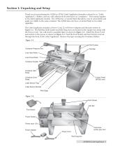
Section 1: Unpacking and Setup Thank you for purchasing the AP360 or AP362 Label Applicator (hereafter referred to as "Label Applicator"). Bottles, cans etc. will collectively be referred to as "containers." This manual applies to two label applicator models. The AP362 has a Control Panel that allows you to count labels and apply two labels to the same container. The AP360 does not have a Control Panel or two-label capability. The Label Applicator includes a Power Cord, 12 volt Power Adapter and the parts shown in Figure 1-1. The Roll Bar, Roll Guides and Roll Drag Arm are located in the supply...
Open the catalog to page 3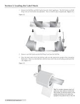
Section 2: Loading the Label Stock 1. Remove the Roll Bar and Roll Guides from the Label Applicator. The Roll Guides and Roll Drag Arm are removable and adjustable. They are held in place magnetically. (Figure 2-1.) Remove one Roll Guide and the Roll Drag Arm from the Roll Bar. Place the label stock roll on the Roll Bar with one side against the upright of the remaining Roll Guide. Place it on the Roll Bar with the loose end of the stock feeding underneath the roll. (Figure 2-2.) Tip! For smaller diameter label roll cores you may need to reverse the Roll Guides so that the bottom of the guides...
Open the catalog to page 4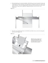
Place the Roll Drag Arm under the Roll Bar. The Roll Drag Arm may be placed on either side of the Roll Bar but the rounded tip of the Roll Drag Arm should be located in the center of the inside of the core. The arm is spring loaded so that there is downward pressure on the inside of the roll. This helps prevent application alignment problems near the end of a roll. (Figure 2-3.) Place the removed Roll Guide back on the Roll Bar and slide it close to, but not touching the label stock roll. (Figure 2-4.) Tip! Roll Guide Uprights must not pinch the label stock roll. (The label stock roll must have...
Open the catalog to page 5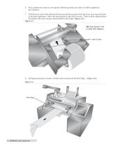
Now position the stock to correspond with the general area where it will be applied to the container. Pull the loose end of the label stock forward and then push it into the Feed Area from the back of the label applicator. Move the label guides to the sides for now. These will be adjusted later. The labels will come out just underneath the Peel Edge. (Figure 2-6.) Figure 2-5. Tip! See Section 5 for a Label Path diagram. Label Guides Pull approximately 12 inches of label stock out beyond the Peel Edge. (Figure 2-6.) Peel Edge
Open the catalog to page 6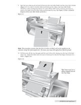
Take the loose label stock and feed it between the Liner Idler Roller and the Liner Drive Roller. (Figure 2-7.) In order to feed the label stock between the rollers, the Liner Idler Roller should be in the unclamped position. For some thicker label stock, it may be necessary to remove the labels from the liner before performing this step. (See Figure 2-10 for a detailed diagram of the Liner Idler Roller positions.) Note: This procedure assumes that the first 12 inches of labels will not be applied to the container using the Label Applicator. Of course, you may still apply these labels by hand....
Open the catalog to page 7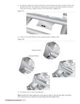
11. If necessary, adjust the position of the liner on the Peel Edge left/right to align the liner with the label stock roll. Also, adjust the Label Sensor using the Label Sensor Bracket so that the Label Sensor Flag is roughly centered on the label stock. (Figure 2-9.) Figure 2-9. 12. Push the Liner Idler Roller into the clamped position. (Figure 2-10.) Figure 2-10. Clamped Position Unclamped Position 13. The labels are now ready for application. Note: Position the Label Applicator on the edge of a table so that the liner falls to the floor. This will prevent excess labels from interfering with...
Open the catalog to page 8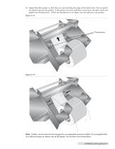
14. Adjust the label guides so that they are just touching the edge of the label stock. Do not pinch the labels between the guides. If the guides are loose pull them away from the label stock and tighten the thumbscrews. When the thumbscrews are tight, you can still move the guides. Figure 2-11. Note: Guides can be removed and swapped to accommodate narrower labels. To accomplish this it is only necessary to remove one of the guides. See Section 6 for instructions.
Open the catalog to page 9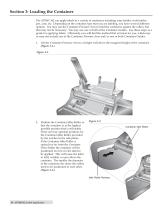
Section 3: Loading the Container The AP360/362 can apply labels to a variety of containers including wine bottles, soda bottles, jars, cans, etc. Depending on the container type that you are labeling, you have several different options. You may use the Container Pressure Arm to hold the containers against the rollers, but that may not be necessary. You may use one or both of the Container Guides. Use these steps as a guide for applying labels. Ultimately, you will find the method that is fastest for you, which may or may not include use of the Container Pressure Arm and/or one or both Container...
Open the catalog to page 10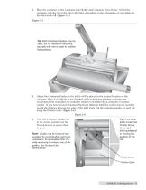
3. Place the container on the Container Idler Roller and Container Drive Roller. Orient the container with the top to the left or the right, depending on the orientation of your labels on the label stock roll. (Figure 3-3.) Tip! Both Container Guides may be used, but for maximum efficiency, typically only one is used to position the container. 4. Adjust the Container Guides so the labels will be placed in the desired location on the container. Since it is difficult to get the label stock in the same position each time, we recommend that you adjust the container relative to the label stock using...
Open the catalog to page 11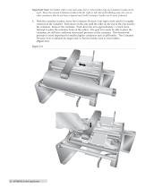
Important Note: For bottles with a neck such soda, beer or wine bottles only one Container Guide can be used. Move the unused Container Guide to the far right or left side of the labeling area. For cans or other containers that do not have a tapered neck, both Container Guides can be used, if desired. 6. With the container in place, move the Container Pressure Arm right or left until it is roughly centered on the container. Push down on the arm until the roller on the end of the arm touches the container. Remove the container. Push down the arm approximately 1/2 inch more. Attempt to place the...
Open the catalog to page 12All Primera Technology catalogs and technical brochures
 Impression IP60
2 Pages
 EddieBrochure
4 Pages
 Bravo 4200 Series
56 Pages
 Bravo SE-3
56 Pages
 RW-7
RW-716 Pages
 AP550
AP55032 Pages
 LX1000/LX2000
90 Pages
 LX500/LX500c
52 Pages
 Bravo series
1 Page
 CX1000
4 Pages
 LP130 Laser Marking System
2 Pages
 RX900F
2 Pages
 RX900
RX9002 Pages
 CX-FX series
8 Pages


Archived catalogs
 LX series
1 Page
 LX series_2013
8 Pages
- Automatic labeling machine
- Label printer
- Bottle labelling machine
- Polymer tag
- Ink
- Color printer
- Desktop printer
- Labelling machine for the food industry
- Desktop label printer
- Thermal transfer printer
- White label
- Roll label
- USB interface printer
- Rewinder-winder
- Printable label
- Compact labeling machine
- High-speed labeling machine
- High-resolution printer
- Semi-automatic label applicator
- Packaging label applicator