- Catalogs
- PRECIA MOLEN
- I 400 Programmable weighing indicator
- Products
- Catalogs
- News & Trends
- Exhibitions
I 400 Programmable weighing indicator
1 /2Pages

I 400 Programmable weighing indicator
1 /2Pages
Catalog excerpts
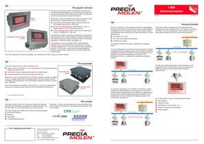
I 400 The graphic terminal General presentation The two main functions of the I 400 graphic terminal are to control the weighing application (in other words management, checking and control of the different transmitters connected to it) and to communicate through the field bus. RACK version Optionally, it may be equipped with various accessories that are functionally complementary to its main functions : & up to two communication type accessories (RS 232, RS 422/485, serial USB or USB key), & up to four input/output type accessories (2 inputs / 4 digital outputs) or 4-20 mA analog outputs), & A Data Storage Devis (DSD) accessory for keeping the history of weighing for Trade Use. The USB key interface, apart from performing a conventional data transfer function, also facilitates updating the application and transferring man-machine dialogue texts thus facilitating adaptation to different trades, languages, etc. STAINLESS STEEL CASING version Occasionally, it may be provided with a measurement interface card thus enabling local management of a load receptor equipped with 1 to 6 load cells (or 8 high impedance sensors). In this case, it may become a simple weighing indicator with features varying from the most simple to the most complex. The I 400 Graphique Terminal is available in a STAINLESS STEEL casing or a RACK version. 10/2006 04-32-00-1 FT General principle Due to its design, the I 400 system provides an upgradeable solution to the different problems that can arise with integration of weighing into the industrial process. They consist of three main elements structured around a CAN Open field bus. These elements are : & the Graphic Terminal, & the associated weight transmitter(s), & the field bus coupler. If the client system manages the entire application and management of the measurement, it can replace the Graphic Terminal. This third configuration only consists of a set of transmitters directly controlled by the client application. Client Field Bus This design enables three basic configurations described below. Coupler CAN Field Bus In a first configuration, the Graphice Terminal assures complete management of the weighing system and controls the different associated automations through a standard application or an application specifically developed for the need. This configuration forms a complete and independent weighing system. T1 T2 From 1 to 31 transmitters Tn The transmitter The main functions of the I 400 transmitter are to : & make a direct connection of 1 to 4 load cells (or 6* load cells through an external connection box), & convert the analog measurement signal to a digital signal, & communicate the information through the field bus. For the most simple applications, the transmitter can be integrated into the Terminal thus being converted into a weighing indicator while maintaining its functional performances. Graphic Terminal CAN Field Bus zinc plated steel version T1 T2 From 1 to 31 transmitters Tn Optionally, it may be equipped with an interface card that contains six digital inputs, six digital outputs and one analog output. All these outputs may be controlled by any equipment in the CAN network (graphic terminal or CLIENT logic controller). The I 400 transmitter is available in two versions : a black zinc plated steel version and a stainless steel version for the most difficult environments. Stainless Steel version * or 8 high impedance load cells. In a second configuration, the addition of a field bus coupler enables the client application to manage all or some of the process without performing functions specific to weighing and possibly some directly related automation operations. This configuration forms an independent weighing system with central data management. Client Field Bus The coupler The main function of the I 400 coupler is to form the interface between the CAN field bus used by the weighing system and the main field bus, if the main field bus is not a CAN bus. Optionally, it may be provided with one or two accessories that can manage communication or delocalized inputs/outputs close to the coupler. The I 400 coupler can interface the CAN bus with several types of field buses including : & Profibus & DeviceNET & TCP/MODBUS Ethernet Graphic Terminal Coupler CAN Field Bus T1 T2 From 1 to 31 transmitters Graphic Terminal The I 400 system is used in many application fields : & Silo weighing & Dosing by batch & Packaging (in drums, bags, etc ...) & Filling or unloading flow regulation & Check weigher & ... Tn / / / / / / / / / / / / / / / / / / / / / / / / / / / / / / / / / / / / / / / / / / / / / / / / / / / / / / / / / / / / / / / / / / / / / / / / / / / / / / / / / / / / / / / / / / / / / / / / / / / / / / / / / / / / / / / / / / / / / / / / / / / / / / // / / / / / / / / / / / / / / / / / / / / / / / / / / / / / / / / / / / / / / / / / / / / / / / / / / / / / / / / / / / / / / / / / / / / / / / / / / / / / / / / / / / / / / Your weighing specialist Illustrations are not contractual. Precia-Molen reserves the right to modify at any time, without prior notice, the information contained in this leaflet. Offices and Factory BP 106 - 07000 Privas - FRANCE Tel. 33 (0) 475 664 600 Fax 33 (0) 475 658 330 E-MAIL [email protected] RCS : 386 620 165 RCS Aubenas / / / / / / / / / / / / / / / / / / / / / / / / / / / / / / / / / / / / / / / / / / / / / / / / / / / / / / / / / / / / / / / / / / / / / / / / / / / / / / / / / / / / / / / / / / / / / / / / / / / / / / / / / / / / / / / / / / / / / / / / / / / / / / // / / / / / / / / / / / / / / / / / / / / / / / / / / / / / / / / / / / / / / / / / / / / / / / / / / / / / / / / / / / / / / / / / / / / / / / / / / / / / / / / / / / / / /
Open the catalog to page 1
I 400 system general block diagram / / / / / / / / / / / / / / / / / / / / / / / / / / / / / / / / / / / / / / / / / / / / / / / / / / / / / / / / / / / / / / / / / / / / / / / / / / / / / / / / / / / / / / / / / / / / / / / / / / / / / / / / / / / / / / / / / / / / / / / / / / / / / / // / / / / / / / / / / / / / / / / / / / / / / / / / / / / / / / / / / / / / / / / / / / / / / / / / / / / / / / / / / / / / / / / / / / / / / / / / / / / / / / / / / / / / / / / / / / / / / / / / / / / / / / / / / / / / / / / / / / / / / / / / / / / / // / / / / / / / / / / / / / / / / / / / / / / / / / / / /...
Open the catalog to page 2All PRECIA MOLEN catalogs and technical brochures
 WEIGH2CONTROL
2 Pages
 ABS-X Ex HOPPER SCALE
2 Pages
 CUBETAPE SCANNER DIMENSIONER
2 Pages
 i 40 Ex 2-21 IECEx
2 Pages
 ROC V4 Weighbridge
2 Pages
 i 35 Weighbridge indicator
2 Pages
 I 200 Ex Indicator
2 Pages
 LABORATORY SCALES
4 Pages
 NEW COMPACT SCALE RANGE
2 Pages
 MAIL AND PARCEL
4 Pages
 i 25 touch
6 Pages
 CKW 410 LOG
2 Pages
 CKW 710
2 Pages
 Weighing scale C 131 AM
2 Pages
 Weighing indicator i5
2 Pages
 Weighing pallet truck TPN-B
2 Pages
 Weighing scale C 130 AB
2 Pages
 Weighing scale C 15 AG-S
2 Pages
 Weighing bars R2 Range
2 Pages
 I 410 SYSTEM
6 Pages
 PRECIA ACCESS
8 Pages
 Light industrial scales
6 Pages
 LOAD CELLS
2 Pages
 HOPPER SCALES
2 Pages
 Product guide
28 Pages
 CONTINUOUS WEIGHING
2 Pages
 CONTINUOUS DOSING
2 Pages
 The new i series
6 Pages
 STORAGE SILOS
2 Pages
 QUARRIES / SAND PITS
2 Pages
 i 20 Weight indicator
2 Pages
 D 20 Remote weight display
2 Pages
 MP: Weighing structure
2 Pages
 CKW Checkweigher
2 Pages
 TVN tension load cell
2 Pages
 Jet?FP P Pallet scale
2 Pages
 MCW Crane scales
2 Pages
 Load cells accessories
2 Pages


Archived catalogs
 Weight indicator I 300
2 Pages


- Rail conveyor
- Belt conveyor
- Management software solution
- Horizontal conveyor
- Tension/compression force transducer
- Steel load cell
- Strain gauge force sensor
- Digital weighing scale
- Stainless steel force transducer
- Weighing force transducer
- Monitoring software solution
- Platform balance
- Stainless steel balance
- Beam type force sensor
- Weighing terminal
- Kilogram weighing scale
- Compression force transducer
- Weighing scale with LCD display
- Digital weight indicator-transmitter