- Catalogs
- Praher Plastics Austria GmbH
- Praher Wafer Check Valve K6 PVC-U
Praher Wafer Check Valve K6 PVC-U
1 /6Pages

Praher Wafer Check Valve K6 PVC-U
1 /6Pages
Catalog excerpts

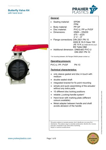
Wafer typ check valve K6 PVC W pe 6 ards: Flange standa wit spring th - M 1.4401 / AISI 316 Mat. -H Hastelloy C-4 (on request 4 t) DIN PN6 und PN10 D ASTM SCH 40 & 80 A (f DN40 – DN only SCH 40 available) for N50 PE100 SDR17 P (N Note installatio information for stub flang on n ges!) Tech hnical features: Spring can be retrofitted a any time without S e at w mechanical processing m Novel valve design with co N onical sealing surface for r highest of req quirements an long serv nd vice life Back-flushed shaft for pre B evention of de eposits Cylindrically housed valve shaft for op C h e ptimal force tr ransmission Easy to moun with screw centering fo DIN2501 E nt w or PN10 and AN class150 P NSI For sizes DN4 to DN200 integrated mounting aid F 40 0, d made of PVC-U with defin breaking point for m ned simple removal For DN 300, integrated su F upporting eye let made o e of galvanized sta ainless steel This do ocument does not constitute a g n guarantee, it is for initial informa ation purposes only. The produ range is continually upgrade uct ed, the des signs and types therefore only reflect the state of the art at the s e e time of printing. Subject to technical m f modifications! © Praher Plastics Austria GmbH DB/EN/D
Open the catalog to page 1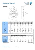
Wafer typ check valve K6 PVC W pe 6 Flap opening ang (W) for different pipe standa gle p ards PVC PN10 0 © Praher Plastics Austria GmbH DB/EN/DEEN/14/01/225C Subject to technica modifications!l
Open the catalog to page 2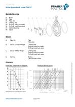
Wafer typ check valve K6 PVC W pe 6 Body Flap Flap clip O-Ring flap g, O-Ring body front side g, O-Ring body bac side g, ck Option spring nal Label Flap Flap clips s O-Ring, f flap O-Ring, b body front side O-Ring, b body back side O-Ring, f flap O-Ring, b body front side O-Ring, b body back side Diagrams: D Pressure – t temperature diagram m Pressure loss diagram Sta arting with 40°C, in ncreased safety fa actor required © Praher Plastics Austria GmbH DB/EN/DEEN/14/01/225C Subject to technica modifications!l
Open the catalog to page 3
Wafer typ check valve K6 PVC W pe 6 Press sure loss 1 ba ar Measureme M ents accor rding to DIN EN 605 D 534-2-3. Pressure lo diagra values determin ed at max opening angle, oss am x. g with PVC P w PN10 pipes and flow medium water at 20°C! s w 2 Opening pre O essure (wit thout spring) Dimen nsion Mount ting position vertical Opening pr O ressure with spring is about 10 mbar higher! h Opening pr O ressure is required differentia pressur to open flap! al re n © Praher Plastics Austria GmbH DB/EN/DEEN/14/01/225C Subject to technica modifications!l
Open the catalog to page 4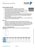
Wafer typ check valve K6 PVC W pe 6 General ins G stallation i informatio on • • • • • • • The v valves are suitable fo a horizon and ve or ntal ertical insta allation Befor mountin a wafer check valv K6 on a pipeline, we are re ng ve w recom mmending to carry ou a complleteness ch ut heck, verify if any da mages y exist and if flap clips, seals and spriing are cor rrect positio oned. Cover Flap clip To gu uarantee th optimum flap open he m ning angle the stub flanges hav to be e ve centr at the b red body centre during th installation. e he After the installa ation the fl lap-clips ha to be...
Open the catalog to page 5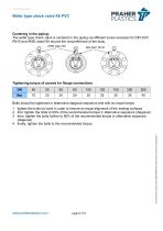
Wafer typ check valve K6 PVC W pe 6 Centering in the piping: Th wafer ty check valve is ce he ype entered in the piping via different screw re ecesses fo DIN 2501 or PN10 and A ANSI class150 around the circu umference of the body. ANSI clas ss150 Ti ightening torque of screws fo flange c f or connectio ons DN Bolts should be tighten in alternative dia d ned agonal sequence and with an e d equal torque © Praher Plastics Austria GmbH DB/EN/DEEN/14/01/225C Subject to technica modifications!l sure an eq 1. tighten th bolts by hand in order to ens . he y o qual alignm ment of the sealing su urfaces...
Open the catalog to page 6All Praher Plastics Austria GmbH catalogs and technical brochures
 Diaphragm valve T4
9 Pages
 2 way ball valve M1
5 Pages
 2 way ball valve S4
5 Pages
 Sampling ball valve S4
4 Pages
 6-way backwash valve
10 Pages
 Butterfly Valve K4
7 Pages
 3 way ball valve S4
7 Pages
 2 way ball valve M1
10 Pages
 Diaphragm valve T4
10 Pages
 Praher Handle Elongation
3 Pages
 Line Strainer S4
5 Pages
 Wafer check valve K4
6 Pages
 Cone check valve S4
4 Pages
 AeratingValve S4
5 Pages