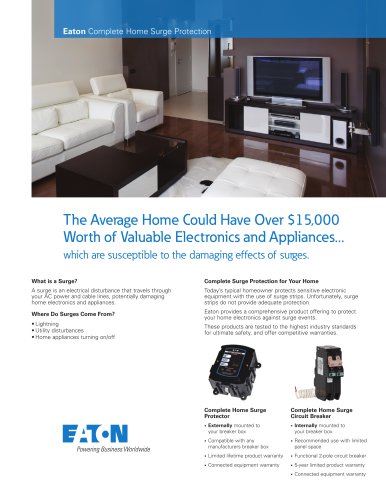
Catalog excerpts

Transfer Switches Transfer Switches Transfer Switch Equipment—Product Overview Product Selection Guide . . . . . . . . . . . . . . . . . . . . . . . . . . . . . . . . . . . Product Description . . . . . . . . . . . . . . . . . . . . . . . . . . . . . . . . . . . . . . . Application Description . . . . . . . . . . . . . . . . . . . . . . . . . . . . . . . . . . . . Contactor-Based Transfer Switches Open Transition, 40–1600 A . . . . . . . . . . . . . . . . . . . . . . . . . . . . . . . . . Open Transition, Service Entrance Rated, 40–1600 A . . . . . . . . . . . . . Closed Transition, 40–1200 A . . . . . . . . . . . . . . . . . . . . . . . . . . . . . . . Open and Closed Transition, 1600–3000 A . . . . . . . . . . . . . . . . . . . . . kW Conversions kW Conversion Chart . . . . . . . . . . . . . . . . . . . . . . . . . . . . . . . . . . . . . . Transfer Switch Features—Standard and Optional Transfer Switch Features Tables . . . . . . . . . . . . . . . . . . . . . . . . . . . . . Feature Description . . . . . . . . . . . . . . . . . . . . . . . . . . . . . . . . . . . . . . . Glossary . . . . . . . . . . . . . . . . . . . . . . . . . . . . . . . . . . . . . . . . . . . . . . . . HMi Remote Annunciator Controller Product Description . . . . . . . . . . . . . . . . . . . . . . . . . . . . . . . . . . . . . . . Features and Benefits . . . . . . . . . . . . . . . . . . . . . . . . . . . . . . . . . . . . . Standards and Certifications . . . . . . . . . . . . . . . . . . . . . . . . . . . . . . . . Technical Data and Specifications . . . . . . . . . . . . . . . . . . . . . . . . . . . . Wiring Diagrams . . . . . . . . . . . . . . . . . . . . . . . . . . . . . . . . . . . . . . . . . Dimensions . . . . . . . . . . . . . . . . . . . . . . . . . . . . . . . . . . . . . . . . . . . . . Automatic Transfer Controllers Product Selection Guide . . . . . . . . . . . . . . . . . . . . . . . . . . . . . . . . . . . ATC-100 Controller . . . . . . . . . . . . . . . . . . . . . . . . . . . . . . . . . . . . . . . . ATC-300+ Controller . . . . . . . . . . . . . . . . . . . . . . . . . . . . . . . . . . . . . . ATC-900 Controller . . . . . . . . . . . . . . . . . . . . . . . . . . . . . . . . . . . . . . . Controller Replacement Guide . . . . . . . . . . . . . . . . . . . . . . . . . . . . . . . Bypass Isolation Power Frame–Based Transfer Switches Open and Closed Transition, 200–5000 A . . . . . . . . . . . . . . . . . . . . . . Power Frame–Based Transfer Switches Open and Closed Transition, 200–5000 A . . . . . . . . . . . . . . . . . . . . . . Molded Case–Based Transfer Switches Open Transition, Manual Operation, 30–1000 A . . . . . . . . . . . . . . . . . Open Transition, Non-Automatic Operation, 30–1000 A . . . . . . . . . . . Open Transition, Automatic Operation, 30–1000 A . . . . . . . . . . . . . . . Bypass Isolation Contactor-Based Transfer Switches Open and Closed Transition, Dual Drawout, 40–1600 A . . . . . . . . . . . Open and Closed Transition, Drawout ATS, Fixed Bypass, 40–1200 A . . . . . . . . . . . . . . . . . . . . . . . . . . . . . . . . .
Open the catalog to page 1
02/05/2018_AN_AN_Major overhaul to complete tab, all pages revised 02/08/2018 All All Revision date changed to February 2018
Open the catalog to page 2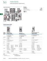
Transfer SwitchesTransfer Switch Equipment—Product OverviewAutomatic Transfer Switches mm Contents Description Product Description . . Application Description Product Selection Guide Transfer Switch Products Catalog Contactor-Based Type AT = Automatic (open transition) CT = Automatic (closed transition) NT = Non-Automatic Refer to Page V2-T5-8 Orientation C = Contactor 3 = AT C-300+ 9 = ATC-900 Mechanism C2 = In-phase only C3 = Time delay neutral (TDN) only C5 = In-phase / TDN transfer Mount X = Fixed mount Contactor-Based 1600-3000 A (up to 600V) AT = Automatic (open transition) CT =...
Open the catalog to page 3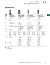
Transfer Switch Equipment—Product Overview Catalog Numbering System Type Contactor-Based, Service Entrance Rated 40-1600 A (up to 480 Vac) AT = Automatic (open transition) Refer to Page V2-T5-14 Molded Case-Based, Manual Molded Case-Based, Non-Automatic Molded Case-Based, Automatic30-1000 A (up to 600 Vac) 30-1000 A (up to 600 Vac) 30-1000 A (up to 600 Vac) MT = Manual (open transition) NT = Non-Automatic (open transition) AT = Automatic (open transition) Refer to Page V2-T5-41 Refer to Page V2-T5-45 Refer to Page V2-T5-48 Orientation C = Contactor H = Horizontal V = Vertical Logic 3 =...
Open the catalog to page 4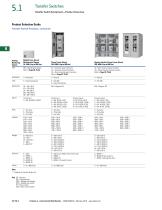
Transfer Switches Transfer Switch Equipment—Product Overview Catalog Molded Case-Based, Numbering Maintenance Bypass System 30-1000 A (up to 480 Vac) Type MB = Maintenance bypass Power Frame-Based 200-5000 A (up to 600 Vac) AT = Automatic (open transition) CT = Automatic (closed transition) NT = Non-Automatic (open transition) Refer to Page V2-T5-55 V = Vertical 9 = ATC-900 E = Electromechanical MG = Magnum DS Bypass Isolation Power Frame-Based 200-5000 A (up to 600 Vac) BI = Open transition bypass isolation CB = Closed transition bypass isolation Refer to Page V2-T5-65 Mount Fixed mount...
Open the catalog to page 5
Transfer SwitchesTransfer Switch Equipment—Product Overview Product Description Eaton's automatic transfer switches are reliable, rugged, versatile and compact assemblies for transferring essential loads and electrical distribution systems from one power source to another. Transfer switches can be supplied in separate enclosures for stand-alone applications or can be supplied as an integral component in the following equipment (see table below). Product Type Section Description Reference Motor Control Centers Vol. 3, Tab 3 Typical Applications All Eaton transfer switches are designed to...
Open the catalog to page 6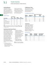
Transfer SwitchesTransfer Switch Equipment—Product Overview There is no center off or neutral position. A three-position device permits the load to be closed on Source 1, closed on Source 2, or unconnected in the center off or neutral position. • Reduction in ground current due to isolated single ground point lowers arc-flash levels and reduces generator damage • Eliminates potential for faults to propagate across overlapping neutral; fully rated fourth pole will handle as a normal operation • Does not generate voltages that exceed normal phase voltage Note: For more detail, reference Eaton...
Open the catalog to page 7All Powerware catalogs and technical brochures
-
5 series UPS
8 Pages
-
Eaton 3S UPS
2 Pages
-
Seismic S-Series Enclosures
4 Pages
-
Blanking Panels
2 Pages
-
Eaton RACKPACKIT
4 Pages
-
Surge protection
8 Pages
-
UPS basics
8 Pages
-
Strategies for design
6 Pages
-
Eaton Marine UPS
7 Pages
-
Eaton 9PHD
2 Pages
-
Power Xpert 9395P
20 Pages
-
Eaton 93PM 30-200kW
12 Pages
-
Eaton 93PS UPS
9 Pages
-
Eaton 93PS IT
4 Pages
-
Eaton 93E UPS 80-200kVA
4 Pages
-
Hot Sync Technology
2 Pages
-
Eaton Ellipse PRO
2 Pages
-
Eaton Ellipse ECO
2 Pages
-
Eaton 9155/9355 UPS
8 Pages
-
UPS Quick Guide
3 Pages
-
Internet Protection
1 Pages
-
Eaton Protection Station
2 Pages
-
S-Series Enclosures Brochure
20 Pages
-
Eaton 9315 UPS Brochure
12 Pages
-
Eaton 9170+ UPS Brochure
6 Pages
-
5125 Family Brochure
6 Pages
-
Vantage S2 Brochure
16 Pages
-
Eaton 5S
2 Pages
-
Eaton BladeUPS MBM Brochure
2 Pages
-
Eaton 3S UPS
2 Pages
-
Eaton 9130 Rack UPS
4 Pages
-
Eaton 5PX UPS
2 Pages
-
Eaton 5P Tower UPS
2 Pages
-
Eaton 5SC UPS
2 Pages
-
Data Center Line Card
1 Pages
-
Eaton ePDU Product Catalog
48 Pages
Archived catalogs
-
Product catalogue
118 Pages
-
Powerware Product Catalog
40 Pages


