
- Catalogs
- Powersolve Electronics
- PAK3000 Series

PAK3000 Series

PAK3000 Series
Overview
This document appears to be a technical manual or installation instructions related to Powersolve Electronics Ltd.'s AC-DC converters, specifically focusing on features such as Remote Sense and Current Sharing with Remote Sense.
Main Sections and Content Summary
1. Product Information and Contact Details
The document includes contact information for Powersolve Electronics Ltd., located at 8A Arnhem Road, Newbury, RG14 5RU, England, with telephone, fax, and email details, as well as the company website.
2. AC-DC Converter Features
The document references key features of the AC-DC converters, including:
- Remote Sense: A feature that allows the converter to compensate for voltage drops in the wiring between the power supply and the load, ensuring accurate voltage delivery.
- Current Sharing with Remote Sense: A method to balance current load between multiple power supplies connected in parallel, improving reliability and performance.
3. Installation Instructions
Although the detailed installation steps are not fully legible, the document is intended to provide guidance on installing the AC-DC converters, including proper wiring and configuration for Remote Sense and Current Sharing functionalities.
4. Technical Specifications and Parameters
The document likely contains technical specifications, parameters, and possibly diagrams or tables related to the operation and installation of the converters, but these are not clearly extractable from the provided text.
5. Recommendations and Best Practices
There are indications of recommendations for correct installation practices, such as wiring methods and configuration settings to ensure optimal performance and safety.
Critical Information Highlights
- Remote Sense wiring is critical to maintain accurate output voltage at the load.
- Current Sharing requires proper configuration to ensure balanced load distribution among parallel converters.
- Installation must follow manufacturer guidelines to avoid performance issues or damage.
- Contact information is provided for technical support and sales inquiries.
Limitations
The document text is heavily corrupted or encoded, limiting the ability to extract detailed procedural steps, exact specifications, or graphical data.
Conclusion
This document serves as a technical and installation guide for Powersolve AC-DC converters with Remote Sense and Current Sharing features. It emphasizes proper installation and configuration to ensure reliable operation. For detailed procedures and specifications, consulting the original, uncorrupted document or contacting Powersolve Electronics directly is recommended.
Catalog excerpts
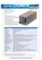
Single Output • Universal AC Input with active PFC • Programmable Output Voltage (30%-105% • Programmable Output Current (40%-105% • 3U profile, High Power Density • Forced current sharing for parallel operation • Power OK signal (Power good, logic low) • Remote ON/OFF, Remote Sense function Electrical Specification Input Voltage Power Factor 90-264VAC, 47-63Hz / 127-370VDC. Below 100VAC, derate load linearly to 90% at 90VAC Inrush Current Leakage Current Output Voltage Output Current Voltage Tolerance Voltage Adjust Range Overload Protection Overvoltage Protection ±5.0% typical adjustment by potentiometer 105-110% of rated output power. Constant I Limiting, output latches off, recycle AC input to recover Variable OVP, 120% ±5% of Vout. Output latches off, recycle AC input to recover Over Temperature Protection Auxiliary Power 80±5°C. Shuts down output, recovers automatically when temperature goes down Remote ON/OFF Control External switch or NPN transistor to turn on/off Output Voltage Programming Output Current Programming Operating Temperature Range Operating Humidity Open drain signal low when PSU turns on. Max. sink current 20mA, max. drain voltage 40V Adjustment of output voltage between 30-105% of rated output (see graph) Storage Temperature Range Storage Humidity Temperature Coefficient_ Adjustment of output current between 40-105% of rated output (see graph) -25°C to +60°C. Above 30°C, derate linearly to 70% load at 60°C 10-500Hz, 1G 10min./1 cycle, period 60 mins each along X, Y & Z axes. Safety Standards Withstand Voltage l/P-O/P: 3KVAC, l/P-FG: 1.5KVAC, O/P-FG: 0.5KVAC Isolation Resistance l/P-O/P, l/P-FG, O/P-FG: 100MQ/500VDC Harmonic Current Controlled by power rating & temperature (internal fan). Ensure 50mm free space at each end. 1. All parameters NOT specifically mentioned are measured at 230Vac input, rated load and 25°C ambient temperature 2. Ripple and noise are measured at 20MHz bandwidth by using a 12" twisted pair wire terminated with a 0.1 uF ceramic & 47uF electrolytic capacitors across the output 3. Derating is required at low input voltages. Below 100Vac, derate linearly to 90% load at 90Vac 4. When parallel connected, only one unit may operate if the total output load is less than 5% of rated load 5. The power supply is considered a component which will be installed into a final equipment. The final equipment must be re-confirmed that it still meets EMC Directives Powersolve Electronics Ltd. 8A Arnhem Road, Newbury, RG14 5RU. England
Open the catalog to page 1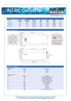
Output Voltage and Current Ratings Mechanical Details Connection Details Input Connector_ Control Connector_ J_ VO+ Local Output Voltage Sense (+) 2_ VS+ Remote Voltage Sense (+) 3_ VS- Remote Voltage Sense (-) 4_ VP- Local Output Voltage Sense (-) 12 PAR Parallel Operation Current Share Powersolve Electronics Ltd. 8A Arnhem Road, Newbury, RG14 5RU. England
Open the catalog to page 2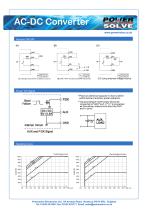
Remote ON/OFF (A) Using internal 5V auxiliary source (C) Using external voltage source * Place an additional capacitor to have a better performance of auxiliary power operation. *Trie grounding of "AUX" power should be connected to "GND" port. If" V-" is connected Derating Curve Powersolve Electronics Ltd. 8A Arnhem Road, Newbury, RG14 5RU. England
Open the catalog to page 3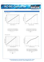
Output Voltage & Current Trim Output Voltage Trim Powersolve Electronics Ltd. 8A Arnhem Road, Newbury, RG14 5RU. England
Open the catalog to page 4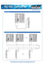
AC-DC Converter www.powersolve.co.uk Remote Sense Current Sharing with Remote Sense Powersolve Electronics Ltd. 8A Arnhem Road, Newbury, RG14 5RU. England Tel: 01635 521858 Fax: 01635 523771 Email: [email protected]
Open the catalog to page 5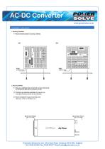
AC-DC Converter Installation Instructions 1-1 Recommended standard mounting methods: 2-1 There are ventilating holes on the front and bacK side panels, do not obstruct; allew 50 mm at least for air flow. 2-2 The Maximum allowable penetraten of screw is 4mm. Incomplete threading should not be penetrated. 2-3 Recommended the torque of mounting screw: Powersolve Electronics Ltd. 8A Arnhem Road, Newbury, RG14 5RU. England
Open the catalog to page 6All Powersolve Electronics catalogs and technical brochures
 TMR-9WI Series
3 Pages
 Power Banks Brochure
6 Pages
 SM15K Series
6 Pages
 ESB101 Series
4 Pages
 TRACOPOWER THI3 Series
3 Pages
 TRACOPOWER TSP-BCMU battery
8 Pages
 EPS SERIES
1 Page
 PUPS22 & 44 Series
2 Pages
 PPS60 Series
1 Page
 EPS SERIES 1000
1 Page
 PS50W Series
4 Pages
 PS50 Series
4 Pages
 TEQ300WIR Series
4 Pages
 TRACO TES1V Series
3 Pages
 TRACO TES1 Series
4 Pages
 CFM10-15 Series
2 Pages
 CFM05 Series
2 Pages
 PSY300 Series
4 Pages
 MDC080 AC
5 Pages
 ESB00163 16A/ESB00323 32A
6 Pages
 ESB101
4 Pages
 ESB00351
2 Pages
 PPT10E
2 Pages
 PSCH30
1 Page
 PSCH15
1 Page
 p-in1504000
3 Pages
 P-IN2902000
3 Pages
 sm3300-interfaces
5 Pages
 ms-adapter
1 Page
 al24-48
1 Page
 Delta catalog
15 Pages
 sx series
4 Pages
 s280
s2802 Pages
 es300
es3004 Pages
 600S
600S2 Pages
 1200S
1200S2 Pages
 sm800
sm8006 Pages
 sm3000
6 Pages
 sm3300
6 Pages
 sm6000
6 Pages
 5u series
2 Pages
 PKS06-USB
2 Pages
 PKS11-USB
3 Pages
 PKS15-2USB
3 Pages
 USB 6 Port Charger
1 Page
 USB 10 Port Charger
1 Page
 USB 10 20 Port USB Hub
1 Page
 MBC-100 Series
5 Pages
 MDC060 Single Output Series
5 Pages
 PLV120-USB
1 Page
 EST150
4 Pages
 ES150 Series
6 Pages
 PMP45-60 Series
3 Pages
 TPM Series
1 Page
 240S Series
2 Pages
 SM1500 Series
6 Pages
 PAE800 Series
6 Pages
 HSEUIreg07201 Series
9 Pages
 HSEUreg07201 Series
5 Pages
 MP Series
10 Pages
 C(AC) Series
8 Pages
 PPS40LB Series
3 Pages
 JB301-JB301D Series
5 Pages
 PP150-PP500 Series
6 Pages
 PAK75-PAK200 Series
3 Pages
 PSO100-PSU100 Series
3 Pages
 PSO80-PSU80 Series
3 Pages
 CFM40-60 Series
2 Pages
 MHP40-100 Series
4 Pages
 CI-I-IT-IV-SS (AC) Series
4 Pages
 CFM40-60
2 Pages
 TOL series
1 Page
 TOF series
1 Page
 PA 150 series
2 Pages
 AHP200 series
2 Pages
 PPS40 Series
3 Pages
 CFM20 Series
2 Pages
 CFM10/15 Series
2 Pages
 Inverter Series
4 Pages
 DC-DC Converters
1 Page
 Desk Top Power Supplies
2 Pages
 Plug Top Power Adaptors
1 Page
 High Density PFC Module
2 Pages
 DC-AC Inverters
1 Page
 Lead Acid Battery Chargers
2 Pages
 AC-DC Converters
10 Pages


- DC power supply
- AC/DC power supply
- Single-output power supply
- Power supply for industrial applications
- Switched-mode power supply
- Battery charger
- On-line UPS
- Lead battery charger
- Electronic equipment power supply
- AC buffered power supply
- Automatic battery charger
- Lead-acid battery charger
- Desktop battery charger
- Lead UPS
- Open frame power supply
- Nickel battery charger
- VRLA UPS
- Smart battery charger
- Ni-Cd battery charger