
- Catalogs
- Power Standards Lab
- microPMU

microPMU

microPMU
The microPMU is a high-resolution device designed to measure and analyze power flows in distribution grids and microgrids. It offers micro-second resolution and precise accuracy, making it suitable for projects requiring detailed synchrophasor measurements for stability and impedance analysis. It supports real-time control applications via the IEEE C37.118.2-2011 interface.
Features
- Ultra-accurate phasor measurements with a Total Vector Error (TVE) of 0.01%.
- Simultaneous recording and streaming of synchrophasors at rates of 100/sec at 50Hz and 120/sec at 60Hz.
- Supports voltage and current phasors, frequency, active/reactive powers, and power factor measurements.
- Compatible with OpenPDC and PSL microPMU plotting software.
- Stores 30 days of micro-synchrophasor measurements in internal memory, downloadable via FTP.
- Configuration and firmware updates via FTP or HTTP.
- Two operational modes: ultra-precise for grid stability analysis and low latency for control applications.
- Easy installation in various locations such as electrical panels and distribution poles.
- Includes a fully isolated GPS receiver with cable delay auto-compensation.
Applications
- Monitoring and understanding the stability of microgrids and distribution grids.
- Event identification and characterization.
- Topology change detection.
- Detection of cyber attack rehearsals at substations.
Specifications
Mains Voltage Input Channels
- Connection: L1, L2, L3, N via PQube 3 screw terminals.
- Frequency Range: 50 Hz, 60 Hz.
- Mains Configuration: Single-phase, split-single-phase, delta, wye/star.
- Nominal Input Voltage Range: 100 VAC ~ 960 VAC L-L.
- Sampling Rate: 25,600 samples/s @ 50Hz and 30,720 samples/s @ 60Hz.
- Isolation: Tested up to 5100VAC to Earth.
- Installation Category: CAT IV for voltages up to 300 VAC L-N.
Current Input Channels
- Measurement Type: External current transformer, voltage-type secondary.
- CT Input Ratio Range: 1:1 to 50000:1.
- Nominal Input: 0.333 V RMS.
- Sampling Rate: 25,600 samples/s @ 50Hz and 30,720 samples/s @ 60Hz.
Power Measurements Definitions
- Watts: Sum of true instantaneous per-phase power.
- Volt-Amps: Sum of per-phase product of RMS voltage and RMS current.
- Power Factor: Ratio of Watts to Volt-Amps.
- VARs: Fundamental VARs.
Modes of Operation
- Ultra Precise Mode: Records to internal memory and streams according to C37.118.2-2011.
- Low Latency Mode: Uses P-Filter and M-Filter for streaming with typical latency of 50 ms.
Technical Specifications
- Dimensions: 4.33 in X 2.89 in X 3.08 in.
- Operating Environment: -20 ~ 65 °C, 5 ~ 95% RH, <2000 m above sea level.
- Power Supply: 24 VAC ±10% or ±24 ~ 48 VDC ±10%, PoE compatible.
- Internal Memory: 32 GB for up to 30 days of data.
- Communication: Ethernet port RJ-45, optional wireless and cell modem.
Catalog excerpts

DATA SHEET microPMU FEATURES • Ultra-accurate phasor measurements: • Fast recording / streaming rate: • Voltage and current phasors, frequency , active / reactive powers, power factor • Fully compatible with OpenPDC, and with PSL microPMU plotting application software • 30 days of micro-synchrophasor measurement stored in internal memory • Configuration / firmware update via Measure and understand the complex and dynamic power flows in distribution grids and microgrids with the microPMU. • Ultra precise mode (for grid stability The microPMU is like a microscope that has micro-second resolution and ultra-precise accuracy needed for distribution grid applications. • Easy installation (can be installed The microPMU is ideal for projects that need ultra-precise synchrophasor measurements for investigating stability and impedance questions. The microPMU can also be used for real-time control applications using the IEEE C37.118.2-2011 interface. • Fully isolated GPS receiver / antenna analysis) or low latency mode (for control applications) in electrical panels, on distribution poles, pad mount transformers..) with cable delay auto-compensation APPLICATIONS • Monitor and understand stability of microgrids or distribution grids, and backup power systems • vent identification and characterization E • opology change detection (open/closed state of switches) T • etection of cyber attacks rehearsals at substations D Above & Beyond Power
Open the catalog to page 1
Part Number: microPMU-DINRaiL-00-000-XXXX MAINS VOLTAGE INPUT CHANNELS 'Amplitude & angle accuracies are dependent when using the Low Latency mode DATA SHEET: microPMU - Nov 5, 2018 v4
Open the catalog to page 2All Power Standards Lab catalogs and technical brochures
 PQube 3e Power Analyser
2 Pages
 PQube 3 Power Analyzer
2 Pages
 ENV2 Data Sheet
2 Pages
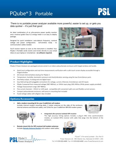 PQ3iaB Portable- Data Sheet
4 Pages
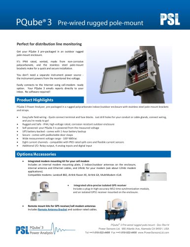
 PQube® 3 Power Analyzers
8 Pages

- Monitoring analyzer
- Analysis software solution
- Measurement software
- Visualization software solution
- Real-time analyzer
- Industrial tester
- Compact analyzer
- Reporting software
- Power quality analyzer
- Electrical network analyzer
- Data analysis software
- Power analyzer
- Electrical equipment tester
- Voltage analyzer
- Graphic analyzer
- Stand-alone test kit
- Power sensor
- Electrical network testing device
- Stability testing device
- Electric power sensor