- Catalogs
- Power Integrations
- TinySwitch-III
TinySwitch-III

TinySwitch-III
Catalog excerpts
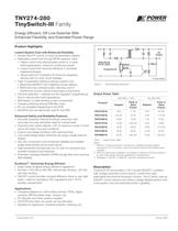
DC Output ΕՕ ՕՕՕՕՕՕՕ ՕՕՕՕՕ Wide-Range HV DC Input D S EN/UV BP/M TinySwitch-III PI-4095-082205 2 Figure 1. Typical Standby Application. 230 VAC ֱ 15%85-265 VAC Product > 3 Peak or OpenFrame Peak or OpenFrame Adapter > 1 Adapter > 1 2 2 TNY274P/G 6 W11 W5 W8.5 W TNY275P/G 8.5 W15 W6 W11.5 W TNY276P/G 10 W19 W7 W15 W TNY277P/G 13 W23.5 W8 W18 W TNY278P/G 16 W28 W10 W21.5 W TNY279P/G 18 W32 W12 W25 W TNY280P/G 20 W36.5 W14 W28.5 W > Table 1. Output Power Table. Notes: 1. Minimum continuous power in a typical non-ventilated enclosed adapter measured at +50 C ambient. Use of an external heatsink will increase power capability.2. Minimum peak power capability in any design or minimum continuous power in an open frame design (see Key Applications Considerations). 3. Packages: P: DIP-8C, G: SMD-8C. See Part Ordering Information. Ю
Open the catalog to page 1
Enable Input and Current Limit State Machine The enable input circuit at the EN/UV pin consists of a low impedance source follower output set at 1.2 V. The current through the source follower is limited to 115 5.85 V Regulator and 6.4 V Shunt Voltage Clamp > A. When the current out of this pin exceeds the threshold current, a low logic level (disable) is generated at the output of the enable circuit, until the current out of this pin is reduced to less than the threshold current. This enable circuit output is sampled at the beginning of each cycle on the rising edge of the clock signal. If high,...
Open the catalog to page 3
Adaptive Switching Cycle On-Time Extension Adaptive switching cycle on-time extension keeps the cycle on until current limit is reached, instead of prematurely terminating after the DC Current Limit The current limit circuit senses the current in the power MOSFET. When this current exceeds the internal threshold (I > Over Temperature Protection The thermal shutdown circuitry senses the die temperature. The threshold is typically set at 142 C with 75 аC hysteresis. When the die temperature rises above this threshold the power MOSFET is disabled and remains disabled until the die temperature falls...
Open the catalog to page 4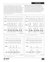
PI-2749-082305 PI-2667-082305 Figure 6. Operation at Near Maximum Loading. Figure 7. Operation at Moderately Heavy Loading. Figure 8. Operation at Medium Loading. V DRAINV EN > PI-2377-082305 PI-2661-082305 Figure 9. Operation at Very Light Load.
Open the catalog to page 5
Current Limit Operation Each switching cycle is terminated when the DRAIN current reaches the current limit of the device. Current limit operation provides good line ripple rejection and relatively constant power delivery independent of input voltage. BYPASS/MULTI-FUNCTION Pin Capacitor The BYPASS/MULTI-FUNCTION pin can use a ceramic capacitor as small as 0.1 F for decoupling the internal power supply of the device. A larger capacitor size can be used to adjust the current limit. For TNY275-280, a 1 F BP/M pin capacitor will select a lower current limit equal to the standard current limit of...
Open the catalog to page 7
V of margin to EN55022 Class B conducted EMI limits.For design fl exibility the value of C7 can be selected to pick one of the 3 current limits options in U1. This allows the designer to select the current limit appropriate for the application. Standard current limit (I Undervoltage lockout is confi gured by R5 connected between the DC bus and EN/UV pin of U1. When present, switching is inhibited until the current in the EN/UV pin exceeds 25 A. This allows the startup voltage to be programmed within the normal operating input voltage range, preventing glitching of the output under abnormal low...
Open the catalog to page 9
Primary Clamp Circuit A clamp is used to limit peak voltage on the DRAIN pin at turn off. This can be achieved by using an RCD clamp or a Zener (~200 V) and diode clamp across the primary winding. In all cases, to minimize EMI, care should be taken to minimize the circuit path from the clamp components to the transformer and TinySwitch-III. > Thermal Considerations Y-Capacitor The four SOURCE pins are internally connected to the IC lead frame and provide the main path to remove heat from the device. Therefore all the SOURCE pins should be connected to a copper area underneath the TinySwitch-III...
Open the catalog to page 10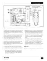
Safety Spacing > Y1-Capacitor +- Output FilterCapacitorMaximize hatched copper areas ( ) for optimum heatsinking > HV Input Filter CapacitorOutputRectifier PRI Transformer BIAS SEC D PRI C BP/MEN/UV BIAS > TinySwitch-III SSSS > BP Opto-coupler > DCOUT +- > PI-4368-042506 Figure 15. Recommended Circuit Board Layout for TinySwitch-III with Undervoltage Lock Out Resistor. the BP/M pin solder pad preventing the design from starting up. Designs that make use of the undervoltage lockout feature by connecting a resistor from the high voltage rail to the EN/UV pin are not affected.If the contamination...
Open the catalog to page 11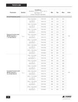
Circuit Protection (cont.) Reduced Current Limit (BP/M Capacitor = 1 di/dt = 50 mA/ s T > J = 25 аCSee Note ETNY274P196210233 mA TNY274G196210237di/dt = 55 mA/ s T > J = 25 CSee Note ETNY275P233250277TNY275G233250283di/dt = 70 mA/ s T > J = 25 аCSee Notes E TNY276P256275305TNY276G256275311di/dt = 90 mA/ s T I > LIMITred J = 25 CSee Notes ETNY277P326350388TNY277G326350396di/dt = 110 mA/ F) See Note D s T > J = 25 аCSee Notes ETNY278P419450499TNY278G419450509di/dt = 130 mA/ s T > J = 25 CSee Notes ETNY279P512550610TNY279G512550622di/dt = 150 mA/ s T > J = 25 аCSee Notes ETNY280P605650721TNY280G605650735...
Open the catalog to page 14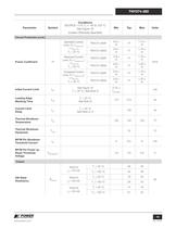
Circuit Protection (cont.)Power Coeffi cient > 2 2 f1.12 ЗI f = I > 2 2 LIMIT(TYP)2 f fI fA > OSC(TYP) 2 T > 2 f1.16 חI > 2 J = 25 CTNY274-280P0.9 ЗI fI fReduced Current Limit, I > 2 2 2 fI f1.16 I > 2 fTNY274-280G0.9 חI I > 2 fStandard Current Limit, I f = I > LIMITred(TYP)2 2 f HzTNY274-280G0.9 חI > OSC(TYP) 2 T > 2 f1.20 I > 2 J = 25 װCTNY274-280P 0.9 I fI fIncreased Current Limit, I > 2 2 f1.16 חI f = I > 2 2 LIMITinc(TYP)2 f fI fTNY274-280G0.9 חI > OSC(TYP) 2 T > 2 f1.20 I > 2 J = 25 װCTNY274-280P0.9 I fI f Initial Current Limit I See Figure 19T > INIT mA > J = 25 װC, See Note G0.75 I >...
Open the catalog to page 15All Power Integrations catalogs and technical brochures
 InnoSwitch3-AQ
28 Pages
 InnoSwitch4-CZ
30 Pages
 LinkSwitch-TNZ
24 Pages
 2SIS0400T2C0C-33
10 Pages
 2SMS0220D2C0C-CM1200DC-34X
8 Pages
 2SML0220D2E0-FF600R17ME4
4 Pages
 2SIL1200T2A0-33
4 Pages
 InnoSwitch3-TN
23 Pages
 ChiPhy
6 Pages
Archived catalogs
 DPA-Switch
34 Pages
 CAPZero
8 Pages
 HiperPLC
26 Pages
 LinkSwitch-TN
20 Pages
 LinkSwitch-II
10 Pages
 TinySwitch-PK
24 Pages
 HiperPLC
26 Pages
 LinkSwitch-CV
20 Pages
 LinkSwitch-LP
16 Pages
 TOPSwitch-HX
48 Pages
 PeakSwitch
24 Pages
 PeakSwitch™ Family
4 Pages
- Bourn And Koch DC power supply
- Bourn And Koch AC/DC power supply
- Bourn And Koch switching power supply
- Bourn And Koch DC/DC converter
- Bourn And Koch isolated DC/DC converter
- Bourn And Koch transistor
- SMD capacitor
- Bourn And Koch high-voltage power supply
- Bourn And Koch SMD DC/DC converter
- High-speed diode
- MOSFET transistor
- Power converter
- Bourn And Koch step-down converter
- Bourn And Koch DC/DC converter for telecom applications
- LED driver
- Printed circuit board power supply
- Adjustable LED driver