
- Catalogs
- Power Integrations
- LinkSwitch-TNZ

LinkSwitch-TNZ

LinkSwitch-TNZ
- Supports buck, buck-boost, and flyback topologies with lossless zero cross signal generation.
- Provides ±3% regulation across line and load with selectable current limit.
- Operates at 66 kHz with frequency jittering to reduce EMI filter complexity.
- Includes X capacitor discharge function in LNK331x models.
- Soft-start feature to limit component stress at start-up.
- Auto-restart for short-circuit and open loop faults.
- Protection against overvoltage, over-temperature, and extended creepage for reliability.
- 725 V MOSFET rating for surge withstand capability.
- Standby supply current is less than 100 mA.
- On/Off control maintains constant efficiency over a wide load range.
- No-load consumption is less than 30 mW with external bias.
- Suitable for home and building automation, dimmers, switches, sensors, appliances, IoT, and industrial controls.
The LinkSwitch™-TNZ family integrates power conversion with lossless AC zero crossing signal generation, reducing component count by 40% or more. It supports various converter topologies and includes a 725 V power MOSFET, oscillator, and protection circuits.
Pin Functional Description- Z1 and Z2 Pins: For zero cross detect signal generation and X capacitor discharge.
- DRAIN (D) Pin: Connection for power MOSFET drain.
- BYPASS (BP/M) Pin: For external bypass capacitor and mode selector for current limit.
- FEEDBACK (FB) Pin: Controls MOSFET switching and provides line overvoltage protection.
- SOURCE (S) Pin: Power MOSFET source connection and ground reference.
Uses ON/OFF control to regulate output voltage, incorporating an oscillator, feedback circuit, 5.0 V regulator, and protection features. Includes frequency jittering to minimize EMI emissions and a soft-start feature to reduce stress at power-up.
Protection Features- Over-Temperature Protection: Disables MOSFET when die temperature exceeds 142 °C.
- Current Limit: Senses current in the MOSFET and turns it off if it exceeds the threshold.
- Auto-Restart: Engages during fault conditions like output overload or short-circuit.
Tables provide typical output current and power for various models under different conditions, highlighting capabilities in buck and flyback configurations.
OverviewThe document provides a detailed technical description of the LinkSwitch-TNZ, covering specifications, operational procedures, design considerations, and application examples.
SpecificationsOperates with an internal clock that samples the FEEDBACK pin to determine the appropriate current limit. Features an ON/OFF control scheme for fast response and tight regulation, minimizing power dissipation and providing line overvoltage protection.
Operational ProceduresEnters auto-restart mode if the FEEDBACK pin current exceeds the threshold for two consecutive cycles. Adjusts current limit based on load conditions, skipping cycles to maintain voltage regulation.
Design ConsiderationsMinimizing transformer leakage inductance for accurate line overvoltage protection and using appropriate components like ultrafast diodes and low-ESR capacitors. Guidelines for selecting components such as the BYPASS pin capacitor, freewheeling diode, and feedback resistors are provided.
Application ExampleAn example of a 0.48 W universal input buck converter is provided, detailing components and their functions, including a zero-crossing detector for efficient operation and noise filtering components.
Topology OptionsCan be used in various topologies, including buck and flyback, with or without optocouplers. Tables for output current and power delivery under different conditions are provided.
Component SelectionRecommendations for selecting components based on desired operation mode (MDCM or CCM) and efficiency requirements. Emphasizes using components with appropriate specifications for optimal performance.
Non-Isolated ConfigurationsDescribes configurations where the output is referenced to neutral, highlighting benefits and considerations for maintaining regulation and minimizing component count.
Product OverviewProvides technical specifications and ordering information for the LinkSwitch-TNZ series, specifically the LNK3307D model, including details on the SO-8C (D Package) and its marking conventions.
SpecificationsOutlines ESD and latch-up test conditions and results, indicating robustness against electrostatic discharge and latch-up at 125°C. MSL rating for various part numbers is also provided, all rated at level 3.
Ordering InformationSpecifies the LinkSwitch product family, TNZ series number, package identifier, and options for tape and reel packaging.
Legal and Warranty InformationPower Integrations reserves the right to make changes to improve reliability or manufacturability. Disclaims warranties, including merchantability and fitness for a particular purpose, and outlines the life support policy.
Contact InformationLists worldwide sales support locations, including contact details for offices in the USA, China, Italy, Japan, Korea, Singapore, Taiwan, the UK, Germany, and India.
Revision HistoryIncludes a revision history, noting updates such as the addition of family part numbers, size 7 parameter updates, and certification bullet points.
Catalog excerpts

LNK33x2-7D LinkSwitch-TNZ Family Energy Efficient Off-line Switcher IC with Best-in-Class Light Load Efficiency and Lossless AC Zero-Cross Detection Product Highlights Highest Performance and Design Flexibility • • • • • Lossless zero cross signal generation Supports buck, buck-boost and flyback topologies Enables ±3% regulation across line and load Selectable device current limit 66 kHz operation with accurate current limit • Allows the use of low-cost off-the-shelf inductors • Reduces size and cost of magnetics and output capacitor • Frequency jittering reduces EMI filter complexity • X capacitor discharge function (LNK331x only) Enhanced Safety and Reliability Features • • • • • • Soft-start limits system component stress at start-up Auto-restart for short-circuit and open loop faults Output overvoltage protection (OVP) Line input overvoltage protection (OVL) Hysteretic over-temperature protection (OTP) Extended creepage between DRAIN pin and all other pins improves field reliability • 725 V MOSFET rating for excellent surge withstand • Nemko (EN62368-1) and CB (IEC62368-1) certifications EcoSmart™– Extremely Energy Efficient • • • • IC standby supply current <100 mA On/Off control provides constant efficiency over a wide load range Easily meets all global energy efficiency regulations No-load consumption <30 mW with external bias Home and building automation Dimmers, switches and sensors with and w/o Neutral wire Appliances IoT and industrial controls Description The LinkSwitch™-TNZ family of ICs combine power conversion with lossless generation of AC zero crossing signal used typically for system clock and timing functions. Designs using the highly integrated LinkSwitch-TNZ ICs are more flexible than discrete implementations reducing component count by 40% or higher. Besides enabling 80+ efficiencies in low power flyback designs, very low consumption at light loads enabled by On/Off control allow for more functions (display, wireless connectivity, sensors etc.) to be active during system standby. The device family supports buck, buck-boost and flyback converter topologies. Each device incorporates a 725 V power MOSFET, oscillator, a high-voltage switched current source for self-biasing, frequency jittering, fast (cycle-by-cycle) current limit, hysteretic thermal shutdown, and output and input overvoltage protection circuitry onto a monolithic IC. LinkSwitch-TNZ ICs consume <100 mA current in standby resulting in power supply designs that can meet no-load and standby regulations worldwide. MOSFET current limit modes can be selected through the BYPASS pin capacitor value. The high current limit level provides maximum continuous output current while the low level permits using very low-cost and small surface mount inductors. A full suite of protection features enables safe and reliable power supplies protecting the device and the system against input and output overvoltage faults, device over-temperature faults, lost regulation, and power supply output overload or short-circuit faults. www.power.com + Zero Cross Signal PI-9175-060820 Figure 1. Typical Buck Converter Application (See Application Examples Section for Flyback and other Circuit Configurations). Output Current in Buck Table1 Product LNK33x2D Table 1. Output Power Table. Notes: 1. Typical output current in a non-isolated buck converter with devices operating at default current limit and adequate heat sinking. Output power capability depends on respective output voltage and thermal requirements. See Key Applications Considerations section for complete description of assumptions, including fully discontinuous conduction mode (DCM) operation. 2. Mostly discontinuous conduction mode. 3. Continuous conduction mode. Output Power in Flyback Table6 Product Table 2. Output Power Table. Notes: 4. Maximum practical continuous power in an open frame design with adequate heat sinking, measured at 25 °C ambient. 5. LNK33x6 is recommended in Flyback for highest efficiency. 6. See Key Application Considerations section for complete description of assumptions. This Product is Covered
Open the catalog to page 1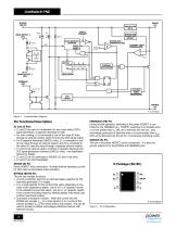
FAULT PRESENT BYPASS PIN CAPACITOR DETECT AUTO-RESTART COUNTER CLOCK RESET CURRENT LIMIT COMPARATOR + JITTER CLOCK ISUPPLY ZERO-DETECT 2 (Z2) THERMAL SHUTDOWN LEADING EDGE BLANKING Figure 3. Functional Block Diagram. Pin Functional Description Z1 and Z2 Pins • Z1 and Z2 are used in combination for zero cross detect (ZCD) signal generation, X capacitor discharge or both. • For zero crossing, Z1 is connected to one of the input AC lines through an external resistor while Z2 forms the ZCD signal output. • For X capacitor discharge (LNK331x only), Z1 is connected to one AC line input through an external...
Open the catalog to page 2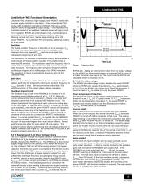
LinkSwitch-TNZ LinkSwitch-TNZ Functional Description Oscillator The typical oscillator frequency is internally set to an average of fOSC (66 kHz). Two signals are generated from the oscillator: the maximum duty cycle signal (DC(MAX)) and the clock signal that indicates the beginning of each cycle. The LinkSwitch-TNZ oscillator incorporates circuitry that introduces a small amount of frequency jitter, typically 4 kHz peak-to-peak, to minimize EMI emission. The modulation rate of the frequency jitter is set to 1 kHz to optimize EMI reduction for both average and quasipeak emissions. The frequency...
Open the catalog to page 3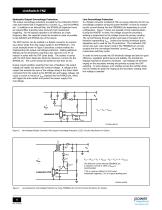
LinkSwitch-TNZ Hysteretic Output Overvoltage Protection The output overvoltage protection provided by the LinkSwitch-TNZ IC uses auto-restart that is triggered by a current >IBPSD into the BYPASS pin. In addition to an internal filter, the BYPASS pin capacitor forms an external filter providing noise immunity from inadvertent triggering. For the bypass capacitor to be effective as a high frequency filter, the capacitor should be located as close as possible to the SOURCE and BYPASS pins of the device. The OVP function can be realized in a flyback converter by connecting a Zener diode from the...
Open the catalog to page 4All Power Integrations catalogs and technical brochures
 InnoSwitch3-AQ
28 Pages
 InnoSwitch4-CZ
30 Pages
 2SIS0400T2C0C-33
10 Pages
 2SMS0220D2C0C-CM1200DC-34X
8 Pages
 2SML0220D2E0-FF600R17ME4
4 Pages
 2SIL1200T2A0-33
4 Pages
 InnoSwitch3-TN
23 Pages
 ChiPhy
6 Pages
Archived catalogs
 DPA-Switch
34 Pages
 CAPZero
8 Pages
 HiperPLC
26 Pages
 LinkSwitch-TN
20 Pages
 LinkSwitch-II
10 Pages
 TinySwitch-PK
24 Pages
 HiperPLC
26 Pages
 LinkSwitch-CV
20 Pages
 LinkSwitch-LP
16 Pages
 TinySwitch-III
24 Pages
 TOPSwitch-HX
48 Pages
 PeakSwitch
24 Pages
 PeakSwitch™ Family
4 Pages
- DC power supply
- AC/DC power supply
- Switched-mode power supply
- DC-DC converter
- Isolated DC-DC converter
- Transistor module
- SMD capacitor
- High-voltage power supply
- High-speed diode
- SMD DC-DC converter
- MOSFET transistor
- Power converter
- Step-down DC-DC converter
- DC/DC converter for telecom applications
- Printed circuit board power supply
- LED driver
- Adjustable LED driver