
- Catalogs
- Power Integrations
- HiperPLC

HiperPLC

HiperPLC
The PLC810PG is an integrated controller designed for power factor correction (PFC) and LLC resonant converters, aimed at reducing external components and enhancing efficiency. It features frequency and phase synchronization, noise and EMI reduction, comprehensive fault handling, and zero voltage switching (ZVS) for high efficiency. It is suitable for applications such as LCD TV power supplies and LED street lighting.
- Integrated PFC and LLC controllers with half-bridge drivers.
- Continuous conduction mode PFC for high efficiency.
- Configurable dead time control and frequency limit.
- Edge collision-avoidance technology for simplified layout.
- Lead and halogen-free package.
- 32” to 60” LCD TV power supplies.
- Off-line power supplies (150 W to 600 W).
- LED street lighting.
The PLC810PG combines PFC and LLC control with integrated high voltage half-bridge drivers. It operates in continuous current mode (CCM) without requiring a sinusoidal input reference, reducing system cost. The LLC controller uses a variable frequency approach for high efficiency, switching MOSFETs at zero voltage. The design supports a typical operating frequency of 100 kHz, with variations based on line and load changes.
- VCC Pins: Power the internal circuitry and drivers, requiring specific bypass capacitors for stability.
- GND Pins: Serve as return nodes for various signals, with specific connections for noise immunity.
- Other Pins: Include HB for half-bridge return, ISP for PFC current sensing, and various gate drive outputs.
The block diagram illustrates the functional elements of the PLC810PG, with separate sections for PFC and LLC control. The device is powered through VCC and VCCL pins, with an internal regulator providing a 3.3 V rail for low voltage circuits.
The PFC section is a boost converter that conditions input current to be sinusoidal and in phase with input voltage. It operates in CCM under normal conditions and may enter DCM under light loads. The PFC controller does not require input voltage sensing, simplifying design. It includes features for overcurrent protection, voltage regulation, and phase alignment to minimize noise and improve performance.
The PLC810PG LLC controller is designed for half-bridge topologies, utilizing two switches to drive a resonant tank and power transformer. It operates at two resonant frequencies: series and parallel. The controller typically functions at a frequency slightly above the series resonant frequency to minimize switching losses through zero voltage switching.
The nominal operating frequency is 100 kHz, but it can exceed 250 kHz to regulate output voltage under varying conditions. The maximum frequency is set using a resistor on the FMAX pin, which also determines the LLC dead time interval. The FBL pin modulates the switching frequency for voltage regulation, with the FMAX pin setting an upper limit to ensure zero voltage switching.
The LLC controller includes a soft start feature to prevent excessive currents during startup. Overcurrent is detected via a sense resistor, with fast and slow thresholds to protect against catastrophic failures and overload conditions, respectively.
The non-overlap generator creates signals to drive the LLC MOSFETs, ensuring zero voltage switching and reducing diode losses. The startup process involves the PFC MOSFET switching once VCC reaches the startup voltage.
The document provides a schematic for a 280 W LCD TV power supply using the PLC810PG and TinySwitch-III. The design includes PFC and LLC stages for high power outputs and a standby power supply. EMI filtering, inrush limiting, and PFC stage components are detailed, highlighting the use of low-cost materials and efficient design choices.
The LLC stage uses MOSFETs in a half-bridge configuration, with components for current sensing and overload protection. The secondary outputs are rectified and filtered to provide various voltage outputs.
The bias regulator provides remote on-off functionality and includes a brownout shutdown circuit to prevent voltage glitches during low AC input conditions.
The main controller IC manages input PFC and output LLC stages, with feedback and frequency compensation components detailed. Ground isolation and bypassing strategies are also discussed to minimize noise and ensure stable operation.
The feedback from the LLC output sense/error amplifiers is managed by an optocoupler, with resistor R54 as the load. Diode D16 ensures the optocoupler only affects the LLC feedback pin (FBL). The LLC current sense signal is filtered by R47 and C35, while C23, R42, and D8 provide the bootstrap supply for the high-side MOSFET driver.
The voltage feedback for the LLC converter's 12V and 24V outputs is managed by resistors R64, R66, and R68. Resistor R62 sets the main gain, while R63 and C45 form a phase-lead compensator. Overvoltage protection (OVP) is provided by Zener diodes VR6-7 and D12, D13, which trigger a latch to deactivate the remote on-circuit in case of overvoltage.
The PFC controller operates in continuous conduction mode with an off-duty-cycle control algorithm, eliminating the need for input AC voltage sensing. The PLC810PG PFC circuit is synchronized with the LLC circuit to reduce interference. The PFC section includes current sense and voltage feedback inputs, and a MOSFET gate signal output. The PFC output voltage is regulated by an operational transconductance amplifier (OTA) connected to the VCOMP pin.
The LLC converter is a variable frequency converter, with the FMAX pin controlling the maximum frequency and dead-time. The FBL pin is used for voltage regulation feedback, affecting the LLC switching frequency. The feedback network typically uses a TL431 and an optocoupler for output regulation. The LLC soft start is managed by CSTART, which ensures a gradual increase in frequency to prevent large primary currents during startup.
The ISL pin monitors LLC primary current, with two thresholds for protection. Exceeding the higher threshold immediately shuts down the MOSFETs, while the lower threshold triggers shutdown after 8 consecutive cycles, both invoking an auto-restart mechanism.
The document provides technical specifications and layout recommendations for the PLC810PG, a power management integrated circuit used in power factor correction (PFC) and LLC resonant converter applications. It includes detailed guidelines on layout considerations, absolute maximum ratings, and DC operating characteristics.
The PLC810PG operates within a junction temperature range of -40°C to +125°C and a storage temperature range of -65°C to +150°C. It supports a continuous supply voltage of -0.3 V to 15 V and can handle an LLC voltage (HB pin) of up to 600 V. The power dissipation is capped at 700 mW.
- PFC Powertrain Layout: The PFC MOSFET, diode, and bulk capacitor should be mounted close together with short leads. A high-frequency bypass capacitor (10 nF-47 nF) is recommended to reduce EMI.
- LLC Powertrain Layout: If using two bulk capacitors, one should be near the PFC MOSFET and the other near the LLC MOSFETs. A high voltage decoupling capacitor (10 nF-100 nF) is advised across the HVDC bus and primary return.
- High Voltage Pins: Pins HB, VCCHB, and GATEH should be isolated from low voltage pins to prevent noise coupling. Maintain a spacing of 160 mil (4 mm) between these pins and low voltage nodes.
- Low Voltage Signal Pins: Decoupling capacitors should be mounted close to the IC, with short traces to the pins. External RC low-pass filters are required for several pins to prevent capacitive coupling with high dv/dt nodes.
- Use an RC low-pass filter with a time constant between 100 ns and 200 ns, mounted near the device.
- Run dedicated traces from the GND pin to the PFC MOSFET source and the PFC sense resistor to avoid noise pickup.
- Mount the PFC gate drive circuit close to the PFC MOSFET to optimize performance and reduce EMI.
The document lists the absolute maximum ratings for various parameters, emphasizing that exceeding these limits may cause permanent damage to the PLC810PG.
The document provides detailed DC operating characteristics, including power supply current, undervoltage lockout thresholds, and LLC VCO frequency range. It specifies the minimum, typical, and maximum values for each parameter.
The document includes several figures and tables illustrating layout recommendations, pin configurations, and performance characteristics. Key figures include power elements in a boost converter stage and isolation of high dv/dt pins from low voltage pins.
Catalog excerpts

becomes discontinuous improving light load operation and reducing power line harmonics. PFC and LLC primary side fault management is provided. The phase of the PFC PWM output is dynamically adjusted relative to the LLC phase such that the switching edges do not coincide with noise sensitive events in the PWM and LLC timing circuits. This edge-collision avoidance technology simplifi es power supply layout and improves performance. Phase synchronization reduces EMI spectral components and reduces ripple current in the PFC capacitor. 2 > Rev. E 05/09 www.powerint.com size="-1">
Open the catalog to page 2
ISP Ω due to internal offset current requirements for the ISP pin. The average inductor current (measured over several switching cycles) is used for the PFC control algorithm. This pin also Implements pulse-by-pulse current limiting. Current sense, PFC. It is for sensing the negative voltage on the current sense resistor (which describes PFC inductor current). This sense resistor is connected between PFC MOSFET Source and Bridge -ђ terminal. The signal must pass through an RC low-pass fi lter with a time constant between 100 and 200 ns. The resistor must be no greater than 150 ISL s. The capacitor...
Open the catalog to page 3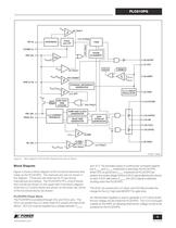
OC +- ISP (3)VCOMP (1)FBP (23) GND (2,19) ISL (22) DVGA and LPF PWM RESETINTERNAL REFERENCEGENERATOR INVERSION 3.3 V LINEARREGULATOR PHASEALIGNMENT > +- PFC FAULT OTAV > FBPREF (6) GATEP(7) VCC (4) VREF(13) VCCHB(12) GATEH(14) HB(16) VCCL(9) GNDL V > +- V > OVH UVLO > +- IN(H) /V > IN(L) V (8) GNDP > +- PFC INHIBIT OC FAULTLLC CLOCK V > UVLO(+) V > UVLO(-) V > SD(H) V > SD(L) +- LLC OFF OVL FAULTLLC OFFLLC FAULTV > REF SOFTSTART CLAMP OVL FAULT OV FAULTV ONE SHOT4096CYCLES LLC CURRENTFEEDBACKRAMP AND CLOCKGENERATOR NON-OVERLAPGENERATOR DEAD TIMEGENERATOR (10) GATEL > +- CLAMP1.2 V FBL (20)FMAX...
Open the catalog to page 5
PLC810PG PFC Control Block The voltage developed across the PFC current sense resistor and applied to the ISP pin is compared against an overcurrent threshold (which has built in hysteresis). This implements a pulse-by-pulse current limit to protect the PFC MOSFET against overcurrent.The ISP pin voltage is also averaged (over several switching cycles), and used as an input to the PFC multiplier.The Discrete Variable Gain Amplifi er, DVGA/LPF block is responsible for averaging the ISP pin voltage (over several switching cycles) and implementing a multiplier as part of the PFC control loop, under...
Open the catalog to page 6
using a resistor connected between the VREF pin and the FMAX pin using the curve in Figure 15. The resistor on the FMAX pin also sets the LLC dead time interval (see Figure 14).The FBL pin provides output voltage regulation. As such the current entering this pin modulates the switching frequency. More current forces a higher switching frequency. The FMAX pin sets an upper limit for the switching frequency to ensure zero voltage switching. Minimum switching frequency is determined by the adjusting minimum bias applied to the FBL pin.If the external feedback circuit attempts to push the LLC controller...
Open the catalog to page 7
LLC Outputs The secondary ouputs of transformer T2 are rectifi ed and fi ltered by D9, D10, C38, C39 and C53 to provide the +12 and +24 V outputs. LLC Stage LLC Input Stage Switched +5 V Main Output MOSFETs Q10 and Q11 form the LLC half-bridge. They are driven directly by the PLC810 via gate resistors R56 and R58. Capacitor C39 is the primary resonating capacitor, and should be a low-loss type rated to tolerate the highest RMS current seen at maximum load. Transformer T2 has a large built-in leakage inductance which acts with C39 to form the series resonant tank. Capacitor C40 is used for local...
Open the catalog to page 10
OVP Zener diodes VR6-7 and D12, D13 sense any overvoltage condition in the 12 V or 24 V outputs. An overvoltage signal from either output is used to trigger a bipolar latch (Q14, Q15, R70, R73), which turns on transistor Q13. This transistor is used to deactivate the remote on-circuit which turns off the primary bias, and hence the PLC810PG. Voltage Feedback The LLC converter 12 V and 24 V outputs are sensed, weighted, and summed by resistors R64, R66, and R68. Resistor R62 is the main gain-setting resistor. Resistor R63 and C45 form a phase-lead compensator which extends the feedback loops crossover...
Open the catalog to page 11
Ω . The programmed current into the FMAX pin controls two parameters:The LLC drive (GATEL and GATEH) dead-time. The smaller the resistor value, the greater the current and the higher the maximum frequency, see Figure 15. The maximum LLC operating frequency. When the FBL pin current increases above the FMAX pin current, the LLC MOSFETs will be shut down. Switching will restart when the FBL pin current drops below the FMAX pin current. The dead-time should be longer than the actual voltage rise and fall times of the LLC half-bridge center-point (longest times at minimum load). If the programmed...
Open the catalog to page 12
Locating the Bulk Capacitor Ω and 1 Ω . If 2 parallel bulk capacitors are used to meet the ripple current requirement, place 1 near the PFC MOSFET, and the second near the LLC MOSFETs. If only one bulk capacitor is used, it is recommended that a high voltage decoupling capacitor, (10 nF- 100 nF), is connected across the HVDC bus and primary return, connected with short traces to the LLC MOSFETs. (See C40 in schematic in Figure 4, and in PCB layout in Figure 9) The LLC converter MOSFETs see high di/dt, and this high voltage decoupling capacitor will reduce EMI. High Voltage Pins Low Voltage Signal...
Open the catalog to page 14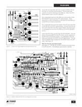
Use an RC low-pass fi lter with time constant between 100 ns and 200 ns, mounted near the device. The low-pass fi lter capacitor should be returned to the GND pin. Mount the PFC sense resistor close to the PFC MOSFET.Run a dedicated trace from the GND pin to the junction of the PFC MOSFET Source and the PFC sense resistor. There should be no other connections on the trace from the GND pin to the PFC/LLC power components.Run a dedicated trace from the resistor of the RC low-pass fi lter on the ISP pin to the PFC sense resistor. To avoid loop pick up from di/dt noise that may effect signal integrity,...
Open the catalog to page 15All Power Integrations catalogs and technical brochures
 InnoSwitch3-AQ
28 Pages
 InnoSwitch4-CZ
30 Pages
 LinkSwitch-TNZ
24 Pages
 2SIS0400T2C0C-33
10 Pages
 2SMS0220D2C0C-CM1200DC-34X
8 Pages
 2SML0220D2E0-FF600R17ME4
4 Pages
 2SIL1200T2A0-33
4 Pages
 InnoSwitch3-TN
23 Pages
 ChiPhy
6 Pages
Archived catalogs
 DPA-Switch
34 Pages
 CAPZero
8 Pages
 HiperPLC
26 Pages
 LinkSwitch-TN
20 Pages
 LinkSwitch-II
10 Pages
 TinySwitch-PK
24 Pages
 LinkSwitch-CV
20 Pages
 LinkSwitch-LP
16 Pages
 TinySwitch-III
24 Pages
 TOPSwitch-HX
48 Pages
 PeakSwitch
24 Pages
 PeakSwitch™ Family
4 Pages
- DC power supply
- AC/DC power supply
- Switched-mode power supply
- DC-DC converter
- Isolated DC-DC converter
- High-voltage power supply
- SMD capacitor
- High-speed diode
- SMD DC-DC converter
- MOSFET transistor
- Power converter
- Step-down DC-DC converter
- DC/DC converter for telecom applications
- Printed circuit board power supply
- LED driver
- Adjustable LED driver