
- Catalogs
- Power Integrations
- HiperPLC

HiperPLC

HiperPLC
The PLC810PG is an integrated controller for power factor correction (PFC) and LLC resonant converters, designed to enhance efficiency and reduce external components. Key features include frequency and phase synchronization, noise and EMI reduction, ripple current reduction, and comprehensive fault handling. It supports Zero Voltage Switching (ZVS) and configurable dead time control.
This controller is ideal for power supplies in 32” to 60” LCD TVs, off-line power supplies from 150 W to 600 W, and LED street lighting.
The PLC810PG integrates PFC and LLC control with high voltage half-bridge drivers, operating in continuous conduction mode (CCM) for efficiency and cost reduction. The LLC controller uses a variable frequency approach to minimize switching losses, supporting zero voltage switching and balanced output currents.
The document details the function of each pin, including requirements for bypass capacitors and connections to ensure proper operation and noise immunity.
The block diagram highlights the PFC and LLC control blocks, powered through VCC and VCCL pins, with an internal linear regulator providing a 3.3 V rail for low voltage circuits.
The PFC control block is a boost converter ensuring sinusoidal input current in phase with the input voltage, operating in CCM and possibly entering DCM under light loads. It includes overvoltage protection, minimum boost voltage detection, and open-loop protection.
The LLC control block manages the resonant converter, ensuring high efficiency through zero voltage switching and precise control of switching frequency, with fault protection and synchronization with the PFC block.
The LLC circuit uses a half-bridge topology to drive a resonant tank and power transformer, operating at two resonant frequencies to enable zero voltage switching and reduce losses.
The controller operates at a nominal frequency of 100 kHz, adjustable up to 250 kHz for voltage regulation, with the FMAX pin setting the maximum frequency and LLC dead time interval.
The controller implements a soft start to prevent excessive currents during startup, with overcurrent detection via a sense resistor.
The non-overlap generator creates signals for the LLC MOSFETs with a 50% duty cycle, with configurable dead time via the FMAX pin.
The PLC810PG begins operation once the VCC voltage reaches the startup threshold, enabling the PFC and LLC stages.
The document includes a schematic for a 280 W LCD TV power supply using the PLC810PG and TinySwitch-III, describing the design with PFC and LLC stages for high power outputs and a standby power supply.
EMI filtering is performed by capacitors and common mode chokes, with a diode bridge rectifying the input AC.
The PFC stage includes an inductor, MOSFET, boost diode, and bulk capacitor, forming a boost converter with continuous mode design for low ripple current and cost efficiency.
The LLC stage uses MOSFETs in a half-bridge configuration, with a resonant capacitor and transformer forming the resonant tank, providing rectified and filtered voltage outputs.
The bias regulator provides remote on-off functionality and includes a brownout shutdown circuit to prevent operation during low AC voltage conditions.
The main controller IC manages input PFC and output LLC stages, with feedback and compensation components ensuring stable operation.
Proper bypassing and ground isolation are emphasized to minimize noise and ensure reliable operation.
The LLC MOSFET returns to the half-bridge through an optional ferrite bead, with feedback managed by an optocoupler and resistor, and the LLC current sense signal filtered for optimal performance.
The secondary control schematic involves voltage feedback with overvoltage protection provided by Zener diodes and a latch to deactivate the remote on-circuit in case of overvoltage.
The PFC controller operates in continuous conduction mode with an off-duty-cycle control algorithm, synchronized with the LLC circuit to reduce interference.
The LLC converter is a variable frequency converter, with the FMAX pin controlling the LLC drive dead-time and maximum operating frequency.
Soft start is implemented to allow the resonant tank to oscillate, preventing large primary currents during startup, with thresholds for immediate shutdown in case of component failure or output overcurrent.
An auto-restart sequence is triggered by fault conditions, ensuring the LLC restarts at frequency FSTART after a specified number of clock cycles.
Detailed layout recommendations are provided for PFC and LLC powertrain components, emphasizing the importance of minimizing loop areas to reduce EMI.
Isolation of high voltage pins from low voltage pins is recommended to prevent noise coupling and erratic operation.
Recommendations include mounting decoupling capacitors close to the IC and using RC low-pass filters to prevent capacitive coupling with high dv/dt nodes.
Guidelines are provided for the placement of gate drive circuits and feedback components to minimize noise and optimize performance.
The document lists the absolute maximum ratings for the PLC810PG, including junction temperature, storage temperature, and various voltage limits.
A table of minimum, typical, and maximum DC operating voltages and currents is provided, detailing parameters like power supply current and undervoltage lockout.
The PLC810PG is packaged in a 24 lead 0.300 PDIP package, conforming to JEDEC specification MS-001.
This document is a technical datasheet or product specification sheet from Power Integrations, detailing the PDIP-24 package marking and related information.
The document includes numerical values likely related to dimensions or specifications, with a revision history indicating updates from November 2008 to August 2009.
Power Integrations reserves the right to make changes to its products and disclaims all warranties, including implied warranties of merchantability and fitness for a particular purpose.
The document notes that the products and applications may be covered by U.S. and foreign patents, with a complete list available on their website.
Contact details for Power Integrations' worldwide sales support locations are provided, including addresses, phone numbers, fax numbers, and email addresses for offices in various countries.
Catalog excerpts
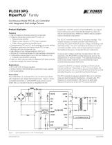
PLC810PG HiperPLC™ Family Continuous Mode PFC & LLC Controller with Integrated Half-bridge Drivers Product Highlights Features • Highly integrated, eliminates external components • Frequency and phase synchronized PFC and LLC • Reduced noise and EMI • Ripple current reduction in PFC output capacitor • Edge collision-avoidance simplifies layout • Comprehensive PFC and LLC fault handling and current limiting • Proprietary continuous conduction mode PFC for high efficiency with low component cost • High efficiency Zero Voltage Switching (ZVS) LLC • Off-time PFC control eliminates AC input sensing components • Configurable, precise dead time control and frequency limit • Prevents hard MOSFET switching • Tight LLC duty cycle symmetry for balanced O/P diode currents • Lead and halogen free Green package Applications • 32” to 60” LCD TV power supplies • Off-line 150 W to 600 W efficiency-optimized power supplies • LED street lighting The DC-DC controller drives an LLC resonant topology. This variable frequency controller provides high efficiency by switching the power MOSFETs at zero voltage, eliminating most switching losses. The LLC controller is built around a current controlled oscillator with a control range selected to support the traditional frequency of operation found in televisions. To ensure zero voltage switching, the dead time of the LLC switching in the PLC810PG is tightly toleranced and can be adjusted with an external resistor. The highside/lowside duty cycle is also closely matched to provide balanced output currents reducing output diode cost. A typical PLC810PG LLC design operates at 100 kHz (under nominal conditions). Depending on the LLC circuit design, the switching frequency can vary from half to three times the nominal operating frequency as a result of line and load changes. Description The PLC810PG is a combined PFC and LLC off-line controller with integrated high voltage half-bridge drivers. Figure 1 shows a simplified schematic of a PLC810PG based power supply where the LLC resonant inductor is integrated into the Standby Supply transformer. The PFC section of the PLC810PG is a universal input continuous current mode (CCM) design that does not require a sinusoidal input reference, thereby reducing system cost and external components. The PFC converter is frequency locked to the LLC to minimize noise and electromagnetic interference. Increasing the PFC frequency in synchronization with the LLC at light loads reduces the current at which the PFC boost converter GNDP GNDL Typical Application Circuit – LCD TV Power Supply.
Open the catalog to page 1
PLC810PG becomes discontinuous improving light load operation and reducing power line harmonics. PFC and LLC primary side fault management is provided. The phase of the PFC PWM output is dynamically adjusted relative to the LLC phase such that the switching edges do not coincide with noise sensitive events in the PWM and LLC timing circuits. This edge-collision avoidance technology simplifies power supply layout and improves performance. Phase synchronization reduces EMI spectral components and reduces ripple current in the PFC capacitor.
Open the catalog to page 2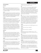
PLC810PG Pin Description VCC Pins VCC VCC powers the small signal analog circuitry inside the IC. A bypass capacitor must be connected from the VCC pin to the GND pin. This capacitor needs to be a 10 mF ceramic capacitor, or a parallel combination of a 10 mF electrolytic capacitor and a 0.1 mF ceramic capacitor. VCCL VCCL is the supply pin for the LLC low side driver. It powers only the LLC low side MOSFET driver and the communications circuitry between the analog circuitry and the LLC drivers. A 1 mF ceramic bypass capacitor must be connected from the VCCL pin to the GNDL pin. This capacitor...
Open the catalog to page 3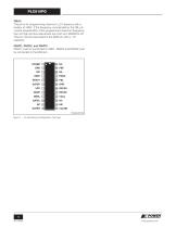
PLC810PG FMAX This pin is for programming maximum LLC frequency with a resistor to VREF. If the frequency commanded by the FBL pin current exceeds 95% of the programmed maximum frequency, the LLC high and low side drivers turn both LLC MOSFETs off. This pin must be decoupled to the GND pin with a 1 nF capacitor. RSVD1, RSVD2, and RSVD3 RSVD1 must be connected to VREF. RSVD2 and RSVD3 must be connected to the GND pin. Pin Numbering and Designation (Top View).
Open the catalog to page 4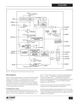
PHASE ALIGNMENT (6) GATEP (7) VCC RESET VUVLO(+) INTERNAL REFERENCE GENERATOR + VREF SOFT ONE SHOT 4096 START CYCLES (13) VCCHB OVL FAULT RAMP AND CLOCK GENERATOR NONOVERLAP GENERATOR DEAD TIME GENERATOR (12) GATEH (14) HB (16) VCCL (10) GATEL Block Diagram of PLC810PG. Reserved Pins are not Shown. Block Diagram Figure 3 shows a block diagram of the functional elements that make up the PLC810PG. The reserved pins are not shown in the diagram. Those pins are reserved for PI use during manufacture and testing. The PLC810PG PFC control blocks and circuits are shown on the upper half of the block...
Open the catalog to page 5
PLC810PG PLC810PG PFC Control Block The PLC810PG PFC is a boost converter which conditions the average input current to make it (typically) sinusoidal and in phase with the input voltage. In normal operation the PFC operates in continuous conduction mode (CCM). Under light load, depending on the PFC inductor value, the converter may enter a discontinuous conduction mode (DCM). The PLC810PG PFC controller does not need to sense the input voltage. The PLC810PG PFC controller exploits the fact that the input voltage (VIN) is effectively constant over a few adjacent switching cycles, because the...
Open the catalog to page 6
PLC810PG using a resistor connected between the VREF pin and the FMAX pin using the curve in Figure 15. The resistor on the FMAX pin also sets the LLC dead time interval (see Figure 14). The FBL pin provides output voltage regulation. As such the current entering this pin modulates the switching frequency. More current forces a higher switching frequency. The FMAX pin sets an upper limit for the switching frequency to ensure zero voltage switching. Minimum switching frequency is determined by the adjusting minimum bias applied to the FBL pin. If the external feedback circuit attempts to push...
Open the catalog to page 7All Power Integrations catalogs and technical brochures
 InnoSwitch3-AQ
28 Pages
 InnoSwitch4-CZ
30 Pages
 LinkSwitch-TNZ
24 Pages
 2SIS0400T2C0C-33
10 Pages
 2SMS0220D2C0C-CM1200DC-34X
8 Pages
 2SML0220D2E0-FF600R17ME4
4 Pages
 2SIL1200T2A0-33
4 Pages
 InnoSwitch3-TN
23 Pages
 ChiPhy
6 Pages
Archived catalogs
 DPA-Switch
34 Pages
 CAPZero
8 Pages
 LinkSwitch-TN
20 Pages
 LinkSwitch-II
10 Pages
 TinySwitch-PK
24 Pages
 HiperPLC
26 Pages
 LinkSwitch-CV
20 Pages
 LinkSwitch-LP
16 Pages
 TinySwitch-III
24 Pages
 TOPSwitch-HX
48 Pages
 PeakSwitch
24 Pages
 PeakSwitch™ Family
4 Pages
- DC power supply
- AC/DC power supply
- Switched-mode power supply
- DC-DC converter
- Isolated DC-DC converter
- Transistor module
- High-voltage power supply
- SMD capacitor
- High-speed diode
- SMD DC-DC converter
- MOSFET transistor
- Power converter
- Step-down DC-DC converter
- DC/DC converter for telecom applications
- Printed circuit board power supply
- LED driver
- Adjustable LED driver