- Catalogs
- Positronic Industries
- Utility Connector Brochure
Utility Connector Brochure

Utility Connector Brochure
- Contact Sizes: 8, 20, and 22
- Current Ratings: Up to 40 amperes nominal
- Terminations: Crimp, wire solder, straight solder, right angle solder, and straight press-fit
- Configurations: Available in multiple variants with standard and high densities
- Qualifications: MIL-DTL-24308, Goddard Space Flight 311P, MIL-C-39029, IP65, IP67
- Features: Offers professional, military, and space-flight quality levels, hot swap capability, AC/DC operation, and a wide variety of accessories.
- Contact Sizes: 16, 20, and 22
- Current Ratings: Up to 13 amperes
- Terminations: Crimp, wire solder, straight solder, and right angle solder
- Configurations: Multiple variants in standard and high densities
- Qualifications: MIL-DTL-28748, MIL-C-39029, CCITT V.35
- Features: Offers industrial and military quality levels, non-corrodible construction, EMI/RFI shielding, and environmentally sealed versions.
- Contact Sizes: 8, 12, 16, 20, and 22
- Current Ratings: Up to 40 amperes nominal
- Terminations: Standard feed through, with flying leads and board mount available upon request
- Configurations: Refer to D-Subminiature and Circular Configurations
- Qualifications: Space-D32
- Features: Designed for high vacuum applications, offers shielded and environmentally sealed versions, and can be mounted on flange assemblies per customer specifications.
Catalog excerpts
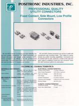
tr.row {} td.cell {} div.block {} div.paragraph {} .font0 { font:8.00pt "Arial", sans-serif; } .font1 { font:9.00pt "Arial", sans-serif; } .font2 { font:10.00pt "Arial", sans-serif; } .font3 { font:15.00pt "Sylfaen", serif; } POSITRONIC INDUSTRIES, INC PROFESSIONAL QUALITY UTILITY CONNECTORS Fixed Contact, Side Mount, Low Profile Connectors GF and GFPL Sries Connectors are high reliability, two and four position connectors. G F Sries connectors are offered with solder and straight solder contacts. GFPL S驩ries connectors are offered in the 90° printed board mount style. Contacts have 0.040 inch (1,02 mm) diame-ters and are rated to 7.5 ampres per contact. G F and GFPL Sries connectors are narrow in width with countersunk side mounting holes. This makes for excep-tionally low profile mounting capabilities. Connectors can be stacked side by side, joined by a center screw (see dia-gram, page 3), enabling a "build your own connecter" situa詭tion with numerous options for polarization. TECHNICAL CHARACTERISTICS MATERIALS AND FINISHES: ELECTRICAL CHARACTERISTICS: Insulator: Glass-filled DAP per MIL-M-14, Type SDG-F. Gray color is standard. Copper alloy, 0.000010 inch (0,25 microns) gold over nickel or copper. Contact Current Ftating: Initial Contact Rsistance: Flash over Voltage: Test Voltage: Insulation Rsistance: Clearance and Creepage: Working Voltage: 7.5 amps, maximum. 0.010 ohms, maximum. 2000 VAC (rms). 1200 VAC (rms). 5 G ohms, minimum. 0.038 inch (0,97 mm) minimum. 300 VAC (rms). Fixed Contacts: MECHANICAL CHARACTERISTICS: Fixed Contacts: Maie: Size 20, 0.040 inch (1,02 mm) diameter. Female: Open Entry is standard. "Closed Entry" available on solder style for high reliabil驭ity applications. Contact Rtention In Insulator: 10 Ibs. (44.5 N), minimum. CLIMATIC CHARACTERISTICS: Temprature Range: -55°C to +125°C. Damp Heat, Steady State: 21 days. Contact Termination: 0.046 inch (1,17 mm) internai diameter on solder style contact for 20 AWG (0,5 mm^) wire, maximum. 0.025 inch (0,64 mm) diameter printed board mount style. Friction. Locking Systems: Polarization: Mechanical Op驩rations: Open Entry Contacts: Gender positioning of contacts. 500 oprations per IEC 512-5. 1,000 oprations per IEC 512-5. Closed Entry Contacts:
Open the catalog to page 1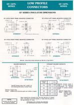
tr.row {} td.cell {} div.block {} div.paragraph {} .font0 { font:4.00pt "Arial", sans-serif; } .font1 { font:6.00pt "Arial", sans-serif; } .font2 { font:7.00pt "Arial", sans-serif; } .font3 { font:8.00pt "Arial", sans-serif; } .font4 { font:9.00pt "Arial", sans-serif; } .font5 { font:10.00pt "Arial", sans-serif; } .font6 { font:16.00pt "Georgia", serif; } .font7 { font:15.00pt "Sylfaen", serif; } GF / GFPL LOW PROFILE GF / GFPL sries CONNECTORS SER,ES GF SERIES INSULATOR DIMENSIONS gf 2-pole right panel mounted connector 0.343(8,71)- gf 2-pole left panel mounted connector -0.125(3,18) -0.343(8,71)...
Open the catalog to page 2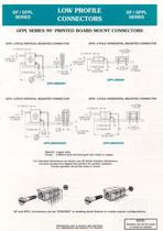
tr.row {} td.cell {} div.block {} div.paragraph {} .font0 { font:7.00pt "Arial", sans-serif; } .font1 { font:8.00pt "Arial", sans-serif; } .font2 { font:9.00pt "Arial", sans-serif; } .font3 { font:10.00pt "Arial", sans-serif; } .font4 { font:14.00pt "Franklin Gothic Medium", sans-serif; } .font5 { font:8.00pt "Georgia", serif; } .font6 { font:16.00pt "Georgia", serif; } .font7 { font:15.00pt "Sylfaen", serif; } GF / GFPL LOW PROFILE GF / GFPL sries CONNECTORS SERIES GFPL SERIES 90° PRINTED BOARD MOUNT CONNECTORS GFPL 2-POLE VERTICAL MOUNTED CONNECTOR 0.172(4,37> GFPL 2-POLE HORIZONTAL MOUNTED...
Open the catalog to page 3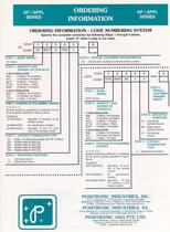
tr.row {} td.cell {} div.block {} div.paragraph {} .font0 { font:7.00pt "Arial", sans-serif; } .font1 { font:8.00pt "Arial", sans-serif; } .font2 { font:9.00pt "Arial", sans-serif; } .font3 { font:10.00pt "Arial", sans-serif; } .font4 { font:17.00pt "Arial", sans-serif; } .font5 { font:18.00pt "Georgia", serif; } .font6 { font:15.00pt "Sylfaen", serif; } GF / GFPL ORDERING GF / GFPL sries INFORMATION SERIES ORDERING INFORMATION - CODE NUMBERING SYSTEM Specify the complte connector by following Steps 1 through 6 below. Insert "0" when a step is not used. GF STEP CODE 1 GF 3M1F a DS5 step 1 - basic...
Open the catalog to page 4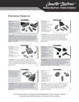
Configurations: Compliance: PICMG 2.11, PICMG 3.0, VITA 41 Multiple variants in a variety of package sizes Contact Sizes: Current Ratings: 0, 8, 12, 16, 20 and 22 To 150 amperes Terminations: Crimp, wire solder, straight solder, right angle solder, straight press-fit and right angle press-fit Power Qualifications : MIL-DTL-24308, Goddard Space Flight 311P, MIL-C-39029, IP65, IP67 D-Subminiature Contact Sizes Configurations : 8, 20 and 22 : Multiple variants in both standard and high densities Current Ratings Terminations : Crimp, wire solder, straight solder, right angle solder and straight press-fit...
Open the catalog to page 5All Positronic Industries catalogs and technical brochures
 PANTHER
12 Pages
 eclipse
8 Pages
 Miniature Circle Hex Connectors
20 Pages
 Baby Cobra King
4 Pages
 Great Golden
11 Pages
 Dragonfly Catalog
19 Pages
 Hermetic Catalog
36 Pages
 Optik-D catalog
10 Pages
 Goldfish power connector catalog
20 Pages
 Cablized Connector Brochure
5 Pages
 Hermetic Connector Catalog
32 Pages
 High Density Rectangular Catalog
43 Pages
 King Cobra Catalog
8 Pages
 Front Runner Catalog
32 Pages
 Circle Hex Catalog
19 Pages
 High Performance D-Sub Catalog
80 Pages
 D-Subminiature Accessories Catalog
40 Pages
 Environmentally Sealed Catalog
56 Pages
 Dual Port Catalog
28 Pages
 D-Subminiature Connector Catalog
104 Pages
 Combo-D Catalog
100 Pages
 VPX Series Catalog
6 Pages
 VPN Series Catalog
6 Pages
 VPB Series Catalog
12 Pages
 Sumo Catalog
17 Pages
 Scorpion Catalog
17 Pages
 Power Connection Systems Catalog
76 Pages
 Infinity Catalog
72 Pages
 Goldfish Catalog
36 Pages
 Compact Power Connector Catalog
124 Pages
 AutoShunt Brochure
13 Pages


- Electrical power supply connector
- Metal connector
- Round connector
- Polymer connector
- Socket electrical connector
- Screw-in connector
- Industrial connector
- Circular connector
- IP67 connector
- Male connector
- Current connector
- Cable connector
- Straight connector
- RF connector
- Screw connector
- Plug-in connector
- Multipole connector
- Nickel-plated brass connector