- Catalogs
- Positronic Industries
- Dragonfly Catalog
Dragonfly Catalog

Dragonfly Catalog
- Dimensional tolerances are provided for contact diameters and other dimensions in millimeters and inches.
- Connector versions include mixed density, power contact, and high-density signal contact connectors, each with specific configurations.
- Insulators are made from glass-filled nylon, with color variations for different versions.
- Contacts are made from copper alloy with gold over nickel plating.
- Hoods and fasteners are made from polypropylene and copper alloy, respectively.
- Contact current ratings vary by size, with size 16 contacts rated at 20.0 amperes continuous.
- Voltage proof and working voltage specifications are detailed for different contact sizes.
- Connectors support various systems, including cable to cable and cable to printed board connections.
- Locking systems and polarization features are integrated into the insulator design.
- Contacts are removable and designed for durability.
- Instructions for connector installation, including panel mount options and recommended tools, are provided.
- Ordering information includes steps to specify connector variants, versions, and mounting options.
- Temperature rise curves and contact performance data are included.
- Contact hole patterns for PCB mounts are detailed for various connector versions.
- Connector Gender: Options include Male (M) and Female (F).
- Type of Contact: Options include removable contacts, solder types, and press-fit compliant terminations.
- Mounting Style and Accessories: Options include no hardware, push-on fasteners, plastic mounting brackets, and panel mount adaptors.
- Environmental Compliance: Compliance with EU Directive 2002/95/EC (RoHS) is available.
- Contact Tools: Includes contact extraction and insertion tools, hand crimp tools, and semi-automatic crimp machines.
- RoHS Compliant Options: Various PCB plating options are available.
- Recommended Drill Hole Sizes: Specific sizes are recommended for different contact sizes and plating types.
- North American Sales Offices: Contact details for the United States, Puerto Rico, Mexico, and Canada.
- European Sales Offices: Contact details for France, Italy, Germany, and the United Kingdom.
- Asia/Pacific Sales Offices: Contact details for Singapore, Japan, South Korea, India, Taiwan, China, Malaysia, New Zealand, and Australia.
- Positronic Industries, Inc: Located in Springfield, MO, USA.
- Positronic Industries, SAS: Located in Auch Cedex 9, France.
- Positronic Asia Pte Ltd: Located in Singapore.
Catalog excerpts

Interconnection Systems High Density Signal and Power Connectors Positronic Industries www.connectpositronic.com
Open the catalog to page 1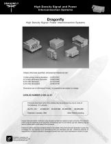
High Density Signal and Power Interconnection Systems High Density Signal/ Power Interconnection Systems Unless otherwise specified, dimensional tolerances are: 1) Male contact mating diameters 2) Contact termination diameters 3) All other diameters 4) All other dimensions Dimensions are in millimeters [inches]. All dimensions are subject to change. Products described within this catalog may be protected by one or more of the following U.S. patents: Other Patents pending. Unless otherwise stated, Positronic code and part number are marked on each connector. The contents of the code are subjected...
Open the catalog to page 2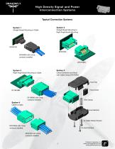
High Density Signal and Power Interconnection Systems Typical Connection Systems Straight Board Mounting to Cable Straight Board Mounting to Right Angle Board Mounting DF04F3N DF07M30 DF04M00 with crimp contacts installed. DF07F4BN Right Angle Board Mounting to Cable Cable Connector and Hood with Cable Clamp DF07F0W1 Hood Insert DF16M00 with crimp contacts installed. Wire Clamp System 4 Cable to Cable Hood Bottom 2x Cable Clamp Screws DF07M00 with crimp contacts installed. 2x Hood Screws DF07F00 with crimp contacts installed. Positronic Industries, Inc www.connectpositronic.com www.positronicasia.com...
Open the catalog to page 3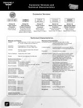
Connector Versions and Technical Characteristics Connector Versions "5^" Version 03 Power Contact Connector Three (3) Size 16 Power Contacts Version 04 Mixed Density Contact Connector Two (2) Size 16 Power Contacts and Two (2) Size 22 Signal Contacts Specify Code 04 in Step 2 Version 07 Power Contact Connector Seven (7) Size 16 Power Contacts Specify Code 07 in Step 2 Version 10 Signal/ Power Contact Connector Ten (10) Size 20 Signal/ Power Contacts Specify Code 10 in Step 2 Version 16 High Density Signal Contact Connector Sixteen (16) Size 22 Signal Contacts Specify Code 16 in Step 2 Hood (W1):...
Open the catalog to page 4
Temperature Rise Curve and Contact PerformanceTemperature Rise CurveTested per IEC 512-3, Test 5a Contact Resistance (Ohms) Temperature Rise (°C) Above curves developed separately using (a) DF04 connectors and AWG 12 wires, and (b) DF07 connectors and AWG 12 wires and (c) DF10 connectors and AWG 18 wires. All power contacts under load. Mating Cycle Above curves developed using DF07 connectors fully populated with size 16 contacts. This information is supplied for reference. Contact wear and change in contact resistance may vary from one application to another. Contact technical sales to discuss...
Open the catalog to page 5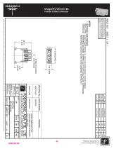
Dragonfly Version 03Female Cable Connector 2zS O —I ^ <?Sc !3gl ;ow2 !m“s ;qf? iipiii illlilf Hslis § ^ w i m n |I|IP sgl|"F luiss g§£si IIIP I§ 3 Positronic Industries, Inc. www.connectpositronic.com
Open the catalog to page 6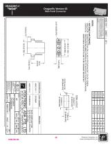
Dragonfly Version 03Male Panel Connector fO X Q slpsaii slis|il| Ogco^«gc5g liulsi ssiiSii »p|s!"3 OH50mwffi 5”5>9zr
Open the catalog to page 7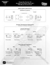
Dragonfly Version 04 Straight and Right Angle (90°) PCB Mount ConnectorsDF04 Outline DimensionsPCB Mount ConnectorFemale 01.93 [00.076] Thru' Contact Termination Dimensions See Step 4 of Ordering Information f A Straight PCB Mount , Specify Code 3 in Step 4 Power contacts Signal contacts Power contacts Signal contacts Right Angle (90°) PCB Mount Specify Code 4 in Step 4 Power contacts Power contacts Not supplied with alignment bar Positronic Industries, Inc www.connectpositronic.com www.positronicasia.com
Open the catalog to page 8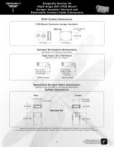
Dragonfly Version 04 Right Angle (90°) PCB Mount (Longer Insulator Version) and Removable Contact Cable Connectors DF04 Outline Dimensions PCB Mount Connector (Longer Insulator) Male only Contact Termination Dimensions See Step 4 of Ordering Information Right Angle (90°) PCB Mount Specify Code 42 in Step 4 Power contacts Signal contacts Removable Contact Cable Connectors Specify Code 0 in Step 4 of Ordering Information Outline Dimensions Male Removable contacts should be allowed to float after terminated and installed in connector body. This enables superior mating performance. Consult factory...
Open the catalog to page 9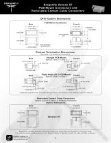
Dragonfly Version 07 PCB Mount Connectors and Removable Contact Cable ConnectorsDF07 Outline Dimensions Contact Termination Dimensions See Step 4 of Ordering Information Straight PCB Mount Specify Code 3 in Step 4 7X3.71 [0.146] 2X 1.84 [0.072] Right Angle (90°) PCB Mount Female 600 [0236] Specify Code 4 in Step 4 Integrated alignment bar and angle bracket, shown for reference only. (Specify code B in Step 5) Removable Contact Cable Connectors Specify Code 0 in Step 4 of Ordering Information Outline Dimensions Removable contacts should be allowed to float after terminated and installed in connector...
Open the catalog to page 10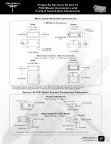
Dragonfly Versions 10 and 16 PCB Mount Connectors and Contact Termination Dimensions DF10 and DF16 Outline Dimensions Male Removable Contact Cable Connectors Specify Code 0 in Step 4 of Ordering Information Male Female Removable contacts should be allowed to float after terminated and installed in connector body. This enables superior mating performance. Consult factory if alignment insert for male contacts is desired. Version 10 PCB Mount Contact Termination Dimensions Straight PCB Mount Specify Code 3 in Step 4 Right Angle (90°) PCB Mount Specify Code 4 in Step 4 Integrated alignment bar and...
Open the catalog to page 11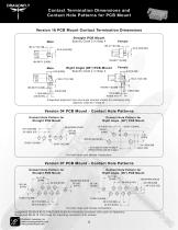
Contact Termination Dimensions and Contact Hole Patterns for PCB MountVersion 16 PCB Mount Contact Termination DimensionsMale Straight PCB MountSpecify Code 3 in Step 4 2X 2.34 [0.092] Right Angle (90°) PCB Mount Female -6.00 [0.236] Specify Code 4 in Step 4 JT 16X3.71 [0.146] Integrated alignment bar and angle bracket shown for reference only. (Specify code B in Step 5) Version 07 PCB Mount - Contact Hole Patterns Contact Hole Pattern for Right Angle (90°) PCB Mount 2X11.30 [0.445] ^MOUNTING HOLES Contact Hole Pattern for Straight PCB Mount 2X11.30 [0.445] 7X02.11 [0.083] 2X2.13 [0.084] -2X6.37...
Open the catalog to page 12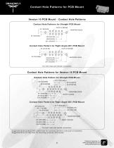
Contact Hole Patterns for PCB Mount Version 10 PCB Mount - Contact Hole Patterns Contact Hole Patterns for Straight PCB Mount 10X01.47 [00.058] MOUNTING HOLES Contact Hole Pattern for Right Angle (90°) PCB Mount 5X3.20 [0.126] 10X01.47 [00.058] MOUNTING HOLES For both male and female connectors. Contact Hole Patterns for Version 16 PCB Mount Contact Hole Pattern for Straight PCB Mount -H 2X11.30 [0.445] |— For both male and female connectors. Suggested 02.OO±O.O8 [0.079±0.003] holes for mounting connector with push-on fasteners. Suggested 02.54 [0.100] holes for mounting connector with screws....
Open the catalog to page 13All Positronic Industries catalogs and technical brochures
 PANTHER
12 Pages
 eclipse
8 Pages
 Miniature Circle Hex Connectors
20 Pages
 Baby Cobra King
4 Pages
 Great Golden
11 Pages
 Hermetic Catalog
36 Pages
 Optik-D catalog
10 Pages
 Goldfish power connector catalog
20 Pages
 Cablized Connector Brochure
5 Pages
 Hermetic Connector Catalog
32 Pages
 Utility Connector Brochure
5 Pages
 High Density Rectangular Catalog
43 Pages
 King Cobra Catalog
8 Pages
 Front Runner Catalog
32 Pages
 Circle Hex Catalog
19 Pages
 High Performance D-Sub Catalog
80 Pages
 D-Subminiature Accessories Catalog
40 Pages
 Environmentally Sealed Catalog
56 Pages
 Dual Port Catalog
28 Pages
 D-Subminiature Connector Catalog
104 Pages
 Combo-D Catalog
100 Pages
 VPX Series Catalog
6 Pages
 VPN Series Catalog
6 Pages
 VPB Series Catalog
12 Pages
 Sumo Catalog
17 Pages
 Scorpion Catalog
17 Pages
 Power Connection Systems Catalog
76 Pages
 Infinity Catalog
72 Pages
 Goldfish Catalog
36 Pages
 Compact Power Connector Catalog
124 Pages
 AutoShunt Brochure
13 Pages


- Electrical power supply connector
- Metal connector
- Round connector
- Polymer connector
- Screw-in connector
- Industrial connector
- Circular connector
- IP67 connector
- Rectangular connector
- Male connector
- Current connector
- Straight connector
- RF connector
- Screw connector
- Plug-in connector
- Multipole connector
- Nickel-plated brass connector