
- Catalogs
- Positronic Industries
- Combo-D Catalog


Combo-D Catalog

Combo-D Catalog
Positronic Industries, established in 1966, specializes in manufacturing high-quality interconnect products. The company is renowned for its service-oriented approach and rapid response times, maintaining a reputation for top-quality connectors through its Complete Capability concept.
- Design & Development: Focuses on creating new connectors and modifying existing ones to meet industry demands, supported by ongoing market research.
- Tooling: Provides 80% of new tooling and supports all manufacturing areas.
- Machining: Utilizes automatic screw machines for crafting contacts and hardware.
- Molding: Molds plastic components with overmold capability.
- Plating: Applies metal finishes conforming to military specifications.
- Quality Assurance: Factories are certified to ISO 9001:2000, AS9100 Rev.B 2004, and ISO 14001 standards.
- Finished Stock Inventory: Maintains large inventories for quick shipments.
- Worldwide Sales & Service: Offers personalized customer service with facilities in multiple countries.
- Dimensional tolerances are specified for various connector components, ensuring precision in manufacturing.
- Products may be protected by several US patents, with additional patents pending.
- CB Series: Available in standard and high-density versions with various contact options.
- CBC Series: Offers crimp removable contacts for multiple applications.
- CBDP Series: Features dual port connectors with various power and signal contact combinations.
- QB Series: Developed for MicroTCA modules, offering board mount and cable connectors for power input.
- ACBDP and ACBMP Series: Combo-D connector savers available in various shell sizes.
- Detailed technical characteristics and ordering information are provided for each connector series.
- Temperature rise curves and contact hole patterns are included for specific connector configurations.
- Positronic's connectors and logos are registered trademarks, and the company complies with EU Directive 2002/95/EC and RoHS standards.
- Minimum hole diameter for 20 AWG wire: 0.028 inch [0.71 mm] for both straight and right angle printed board mounts.
- Power Contacts, Size 8 male: 0.142 inch [3.61 mm] crimp mating diameter.
- Termination diameters for printed board mounts: 0.078 inch [1.98 mm], 0.094 inch [2.39 mm], and 0.125 inch [3.18 mm].
- High Voltage Contacts: Minimum hole diameter of 0.041 inch [1.04 mm].
- Shells: Male shells may be dimpled for EMI/ESD ground paths.
- Polarization: Trapezoidally shaped shells and polarized jackscrews.
- Mounting: Jackscrews, riveted fasteners, and push-on fasteners.
- Locking Systems: Jackscrews and vibration locking systems.
- Mechanical Operations: CBD series open entry contacts for 500 operations, PosiBand closed entry and CBM series for 1,000 operations per IEC 512-5.
- Size 20 Contacts: 7.5 amperes nominal current rating, 0.008 ohms maximum initial contact resistance, 1000 V r.m.s. proof voltage.
- Size 8 Power Contacts: Current ratings vary by termination diameter, with a maximum of 80 amperes for high conductivity material.
- Initial Contact Resistance: 0.0005 ohms max for standard material, 0.00035 ohms max for high conductivity material.
- Proof Voltage: 1000 V r.m.s.
- Insulator Resistance: 5 G ohms.
- Clearance and Creepage Distance: 0.042 inch [1.06 mm] minimum.
- Working Voltage: 300 V r.m.s.
- Temperature Range: -55°C to +125°C.
- Damp Heat, Steady State: 10 days.
- Available in straight and right angle PCB mount contacts.
- Dimensions are provided in inches and millimeters, subject to change.
- Various shell sizes and contact variants are available, with specific dimensions and configurations.
- Suggested printed board hole sizes for different contact termination positions are provided.
- Straight Printed Board Mount Connector: Codes 3, 35, 36, 37
- Right Angle Printed Board Mount Connector: Codes 4, 45, 47
- Compliant Press-Fit Connector: Code 93
Each type has specific dimensions and current ratings, such as 15 or 30 amps nominal for power contacts.
- Materials: Connectors are made from brass or steel with zinc plating and chromate seal, stainless steel, or aluminum with electroless nickel plating. Hoods are available in composite, plastic, brass, steel, or aluminum.
- Contact Types: The connectors feature removable crimp contacts in sizes 22, 16, and 8, suitable for signal, power, and thermocouple applications.
- Performance Standards: They meet IEC 807-7, MIL-DTL-24308, and SAE AS 39029 standards.
- Contact Retention: Signal size 22 contacts have a retention force of 9 lbs, size 16 power contacts 15 lbs, and size 8 power contacts 22 lbs.
- Shells: Male shells may be dimpled for EMI/ESD ground paths, with trapezoidal shapes for polarization.
- Locking Systems: Include jackscrews and vibration locking systems, supporting a minimum of 1000 mechanical operations.
- Size 22 Contacts: Rated for 5 amperes with a proof voltage of 1000 V r.m.s.
- Size 16 Contacts: Standard material rated for 28 amperes, high conductivity material for 40 amperes, with a proof voltage of 1000 V r.m.s.
- Size 8 Contacts: Details provided on page 4.
- Temperature Range: -55°C to +125°C.
- Damp Heat: Steady state for 10 days.
- Combo-Dual Port Series: Offers combinations of power and signal contacts within the same assembly, compliant with IEC 807-2 and DESC 85039 standards.
- Environmental Compliance: Options available per EU Directive 2002/95/EC (RoHS).
- Contact Positions: For 48 Volt connectors, positions A1 and A2 are first to mate, while positions 1 and 2 are last. For 24 Volt connectors, positions A1 and A4 are first to mate.
- Connector Types: Includes Dual Port and Uni Port configurations with typical part numbers provided for each.
- Dimensions: All dimensions are provided in inches and millimeters, with a note that they are subject to change.
- Insulator: Made from glass-filled polyester, UL 94V-0 rated.
- Contacts: Made from copper alloy with optional gold plating over nickel.
- Shells: Available in steel or brass with various plating options.
- Contact Retention: Signal contacts retain 9 lbs, and power contacts retain 22 lbs.
- Operations: ACBDP series supports a minimum of 500 operations, while ACBMP series supports 1,000 operations.
- Contact Current Rating: Size 20 contacts are rated at 7.5 amperes nominal.
- Initial Contact Resistance: 0.008 ohms.
- Connectors can be specified by selecting options from steps 1 through 9, including basic series, connector variants, gender, contact termination, mounting style, shell options, and environmental compliance.
- Special options and compliance with EU Directive 2002/95/EC (RoHS) are available.
- Connectors can be supplied with standard D-subminiature mounting brackets.
- For crimping information and tools, refer to the Application Tools section on pages 81-89.
1. Contact Ratings: Size 8 contacts have a current rating of 70 amperes as per U.L. 1977, with an initial contact resistance of 0.0005 ohms maximum. Proof voltage is 1,000 V r.m.s.
2. Connector Characteristics: Insulator resistance is 5 G ohms, with a clearance and creepage distance of 0.039 inch [1.0 mm] minimum. Working voltage is 300 V r.m.s.
3. Climatic Characteristics: The temperature range is from -55˚C to +125˚C.
Connector Variants and Features:
1. Combo-D Connectors: Available in various shell sizes and configurations, including high-density variants. Contact Technical Sales for availability of specific variants.
2. Jackscrew Systems: Options include rotating and fixed male and female jackscrews, with polarized versions available.
3. Contact Stabilization: Size 8 contacts feature a stabilization mechanism to minimize float and alignment issues during mating.
Ordering Information:
1. Code Numbering System: Connectors are specified by selecting options from steps 1 through 10, including shell size, connector variant, gender, and environmental compliance.
2. Special Options: Additional options are available in the Special Options Appendix.
Electrical and Mechanical Characteristics:
1. High Current Contacts: Size 8 contacts can handle very high currents and are compatible with 6 AWG wire. They feature a closed entry design for maximum mating surfaces and reduced contact resistance.
2. Temperature Rise Curve: Illustrates the relationship between rated current and temperature rise for various connector configurations.
Customization and Unique Features:
1. Customer-Specified Termination Lengths: Positronic offers connectors with custom termination lengths to fit specific application requirements.
2. Removable Contacts: Size 22 removable contacts are available with various finishes and are designed for easy insertion and release.
For further details and technical support, contact Positronic Industries through their website.
- Materials and Finishes: Made from precision machined copper alloy with gold flash over nickel. Optional finishes are available.
- Mechanical Characteristics: Contacts are inserted and released from the rear face of the insulator. Male contacts have a 0.040 inch mating diameter, with female contacts available in closed or open entry designs.
- Electrical Characteristics: Rated for 7.5 amperes nominal current with a maximum initial contact resistance of 0.008 ohms.
- Materials and Finishes: Available in standard and high conductivity copper alloys, both with gold flash over nickel.
- Mechanical Characteristics: Contacts are inserted to the rear and released from the front face of the insulator. Male contacts have a 0.062 inch mating diameter.
- Electrical Characteristics: Standard contacts are rated for 28 amperes, while high conductivity contacts are rated for 40 amperes. Initial contact resistance is 0.0016 ohms for standard and 0.001 ohms for high conductivity materials.
- Materials and Finishes: Available in standard, high conductivity, high voltage, and shielded versions, with various finishes including gold over nickel.
- Mechanical Characteristics: Contacts are inserted to the rear and released from the front face of the insulator. High voltage contacts have a minimum hole diameter of 0.041 inch.
- Electrical Characteristics: High voltage contacts have a flash over voltage of 3600 V r.m.s. and a proof voltage of 2700 V r.m.s. Shielded contacts have a nominal impedance of 50 ohms and specific insertion loss and VSWR values.
- Features a two-piece design separating electrical and mechanical functions, enhancing reliability and reducing the need for annealing.
- Provides higher mechanical reliability and electrical continuity compared to traditional split tine designs.
- Available in different gold thicknesses over nickel, indicated by suffixes such as "-14" and "-15".
- RoHS compliance options are available by adding "/AA" to the part number.
The document provides detailed specifications for various connector components, including dimensions in inches and millimeters. It emphasizes that all dimensions are subject to change.
Procedures:
The document outlines multiple procedures for connecting wires to contacts, including crimping and soldering methods. Each method involves trimming the cable, sliding the ferrule over the jacket, inserting the dielectric and center conductor into the barrel, and securing the connection through crimping or soldering.
Application Tools:
A variety of tools are recommended for the insertion and removal of contacts, including crimping tools, automatic pneumatic crimp tools, and cycle-controlled hand crimp tools. The document provides part numbers for tool selection and emphasizes the use of Positronic tools for optimal results.
Contact Application Tools Cross Reference List:
This section provides a cross-reference list for contact application tools, detailing the appropriate tools for different contact sizes and types. It includes part numbers for handles, crimp tools, positioners, insertion tools, and removal tools.
PCB Hole Sizes for Compliant Press-Fit Connectors:
The document suggests printed board hole sizes for compliant press-fit connectors, with recommendations for different plating options such as tin-lead, copper, immersion tin, immersion silver, and electroless nickel/immersion gold. It provides specific drill hole sizes and finished hole sizes for each plating type.
Press-Fit User Information:
Instructions are provided for installing connectors using Bi-Spring Power or Omega Signal Press-Fit terminations. The process involves inserting the connector into the PCB or backplane, seating it fully, and securing it with self-tapping screws.
Recommended Tools for Compliant Press-Fit Connectors:
The document lists recommended tools for seating connectors, including connector seating tools with arbor press shafts and replacement pins for female connectors. It specifies part numbers for different shell sizes and connector variants.
Catalog excerpts
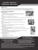
Design & Development Designs new connectors and modifies existing connectors to meet industry requirementsՕ Continuously conducts marketing studies to identify industry needs for new products Ongoing interest in unique connector designs Tooling Օ Tooling support for all manufacturing areas within company Provides 80% of new tooling, punch press dies, molds, jigs and fixtures used at Positronic factory locations worldwide > Machining Molding Finished Stock Inventory Machining Օ Automatic screw machines produce finely crafted contacts and hardware for connector bodies Trained technicians operate...
Open the catalog to page 2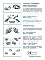
CB series connectors are available in standard densityversions, which have fixed size 20 signal contacts and size 8power, shielded, high voltage and air contacts.High density CB series connectors offer fixed size 22 signal contacts, size 8contacts or size 16 power contacts.These connectors areavailable in various performance levels for best cost/perform- ance ratio.Thermocouple contact options are also available. > CBC series connectors offer crimp removable contacts for sig-nal, power, shielded, high voltage and air contacts applications.These connectors are available in standard and high density...
Open the catalog to page 3
tr.row {} td.cell {} div.block {} div.paragraph {} .font0 { font:7.00pt "Arial", sans-serif; } .font1 { font:10.00pt "Arial", sans-serif; } .font2 { font:13.00pt "Arial", sans-serif; } .font3 { font:15.00pt "Arial", sans-serif; } .font4 { font:23.50pt "Arial", sans-serif; } >OSITRONICCABLIZEDCONNECTORS ^^^^^^^^^^^^^^^^^^^^^^^^^^^^^^^^^^^^^^^^^^^^^^^^^^^^^^^^^^^^^^^^^^^^^^^^^^^^^^^^^^^^^^^^^^^^^^^^^^^^^^^^^^^^^^^^ SAVE TIME AND MONEY! Let Positronic support your connector requirements by cablizing your Oombo-D connector selection. Positronic offers technical support and manufacturing capability...
Open the catalog to page 7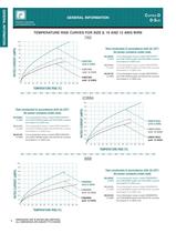
tr.row {} td.cell {} div.block {} div.paragraph {} .font0 { font:5.00pt "Arial", sans-serif; } .font1 { font:5.25pt "Arial", sans-serif; } .font2 { font:7.00pt "Arial", sans-serif; } .font3 { font:8.00pt "Arial", sans-serif; } .font4 { font:10.00pt "Arial", sans-serif; } .font5 { font:11.00pt "Arial", sans-serif; } .font6 { font:16.00pt "Arial", sans-serif; } .font7 { font:18.00pt "Franklin Gothic Medium", sans-serif; } .font8 { font:10.00pt "Lucida Sans Unicode", sans-serif; } .font9 { font:13.00pt "Times New Roman", serif; } .font10 { font:14.00pt "Times New Roman", serif; } GENERAL INFORMATION...
Open the catalog to page 8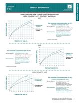
tr.row {} td.cell {} div.block {} div.paragraph {} .font0 { font:5.00pt "Arial", sans-serif; } .font1 { font:5.25pt "Arial", sans-serif; } .font2 { font:7.00pt "Arial", sans-serif; } .font3 { font:8.00pt "Arial", sans-serif; } .font4 { font:9.00pt "Arial", sans-serif; } .font5 { font:9.60pt "Arial", sans-serif; } .font6 { font:11.00pt "Arial", sans-serif; } .font7 { font:16.00pt "Arial", sans-serif; } .font8 { font:18.00pt "Franklin Gothic Medium", sans-serif; } .font9 { font:10.00pt "Lucida Sans Unicode", sans-serif; } .font10 { font:13.00pt "Times New Roman", serif; } GENERAL INFORMATION g...
Open the catalog to page 9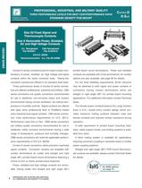
tr.row {} td.cell {} div.block {} div.paragraph {} .font0 { font:5.25pt "Arial", sans-serif; } .font1 { font:7.00pt "Arial", sans-serif; } .font2 { font:8.00pt "Arial", sans-serif; } .font3 { font:9.00pt "Arial", sans-serif; } .font4 { font:11.00pt "Arial", sans-serif; } .font5 { font:13.00pt "Arial", sans-serif; } .font6 { font:14.00pt "Arial", sans-serif; } .font7 { font:22.00pt "Arial", sans-serif; } .font8 { font:14.40pt "Lucida Sans Unicode", sans-serif; } .font9 { font:13.00pt "Times New Roman", serif; } PROFESSIONAL, INDUSTRIAL AND MILITARY QUALITY THREE PERFORMANCE LEVELS FOR BEST COST/PERFORMANCE...
Open the catalog to page 10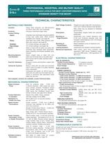
tr.row {} td.cell {} div.block {} div.paragraph {} .font0 { font:7.00pt "Arial", sans-serif; } .font1 { font:8.00pt "Arial", sans-serif; } .font2 { font:9.00pt "Arial", sans-serif; } .font3 { font:9.90pt "Arial", sans-serif; } .font4 { font:10.00pt "Arial", sans-serif; } .font5 { font:11.00pt "Arial", sans-serif; } .font6 { font:13.00pt "Arial", sans-serif; } .font7 { font:7.00pt "Arial Black", sans-serif; } PROFESSIONAL, INDUSTRIAL AND MILITARY QUALITY THREE PERFORMANCE LEVELS FOR BEST COST/PERFORMANCE RATIO STANDARD DENSITY PCB MOUNT ombo D-Sub Positronic Industries connectpositronic.co TECHNICAL...
Open the catalog to page 11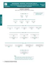
tr.row {} td.cell {} div.block {} div.paragraph {} .font0 { font:7.00pt "Arial", sans-serif; } .font1 { font:8.00pt "Arial", sans-serif; } .font2 { font:10.00pt "Arial", sans-serif; } .font3 { font:11.00pt "Arial", sans-serif; } .font4 { font:13.00pt "Arial", sans-serif; } .font5 { font:16.00pt "Arial", sans-serif; } .font6 { font:7.00pt "Arial Black", sans-serif; } .font7 { font:16.00pt "Arial Black", sans-serif; } .font8 { font:5.00pt "Lucida Sans Unicode", sans-serif; } .font9 { font:13.00pt "Times New Roman", serif; } professional, industrial and military quality three performance levels...
Open the catalog to page 12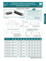
CBD/CBM SERIES
Open the catalog to page 13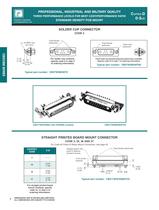
Fixed female jackscrewsFixed femalejackscrewFixed malejackscrew0.345[8.76] 20 AWG max.[0.5 mm > 2 ] > CBD/CBM SERIES 0.125[3.18] > Fixed male and female polarized jackscrews available.Specify code T6 in step 7 of ordering information. > Fixed female jackscrewsSwaged spacer withpush-on fastener, phosphor bronze. > DIMENSIONS ARE IN INCHES [MILLIMETERS].ALL DIMENSIONS ARE SUBJECT TO CHANGE. >
Open the catalog to page 14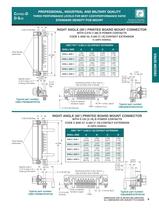
Positronic Industriesconnectpositronic.com 0.220 [5.59] Max. 0.008 Fixed femalejackscrews > 0.220 [5.59] Max. 0.810[20.57] 0.810[20.57] 0.112 [2.84] Typ. ر0.008 0.112[2.84] Typ.0.112[2.84] Typ. 0.125 [3.18] 0.170 [4.32]Nominal Fixed femalejackscrews Specify code 5 or 57 in step 4 of ordering information.Numbering shown is rear view ofmale and face view of female.Push-on fastener,beryllium copper. > DIMENSIONS ARE IN INCHES [MILLIMETERS].ALL DIMENSIONS ARE SUBJECT TO CHANGE. >
Open the catalog to page 15All Positronic Industries catalogs and technical brochures
 PANTHER
12 Pages
 eclipse
8 Pages
 Miniature Circle Hex Connectors
20 Pages
 Baby Cobra King
4 Pages
 Great Golden
11 Pages
 Dragonfly Catalog
19 Pages
 Hermetic Catalog
36 Pages
 Optik-D catalog
10 Pages
 Goldfish power connector catalog
20 Pages
 Cablized Connector Brochure
5 Pages
 Hermetic Connector Catalog
32 Pages
 Utility Connector Brochure
5 Pages
 High Density Rectangular Catalog
43 Pages
 King Cobra Catalog
8 Pages
 Front Runner Catalog
32 Pages
 Circle Hex Catalog
19 Pages
 High Performance D-Sub Catalog
80 Pages
 D-Subminiature Accessories Catalog
40 Pages
 Environmentally Sealed Catalog
56 Pages
 Dual Port Catalog
28 Pages
 D-Subminiature Connector Catalog
104 Pages
 VPX Series Catalog
6 Pages
 VPN Series Catalog
6 Pages
 VPB Series Catalog
12 Pages
 Sumo Catalog
17 Pages
 Scorpion Catalog
17 Pages
 Power Connection Systems Catalog
76 Pages
 Infinity Catalog
72 Pages
 Goldfish Catalog
36 Pages
 Compact Power Connector Catalog
124 Pages
 AutoShunt Brochure
13 Pages


- Electrical power supply connector
- Metal connector
- Circular connector
- Polymer connector
- Screw-in connector
- Industrial connector
- IP67 connector
- Rectangular connector
- Male connector
- Current connector
- Straight connector
- RF connector
- Screw connector
- Nickel-plated brass connector
- Crimp connector
- Voltage connector
- Multipole connector