RSB001 - RS-4022 Driver
1 /4Pages

RSB001 - RS-4022 Driver
1 /4Pages
Catalog excerpts

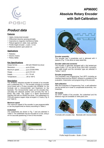
Product data Features • Single-ended to differential RS422 • Small size, easy to connect • Connectors for flexibility or soldered flat cables for minimum profile height The RS422 Interface Board converts 5V TTL or CMOS single-ended encoder signals to RS422 differential signals. The ASSIST Interface Board and the ASSIST software allow to configure and/or program the encoder. Encoder Power The three ways to power the encoder are explained below. Encoder power from RS422: put the Encoder Power jumper in place. Do not connect the ASSIST Board. Encoder power from ASSIST Board: remove the Encoder Power jumper. The RS422 power supply may be connected or not. Configure the encoder using the ASSIST Board, then switch to RS422 power: 1) Remove the Encoder Power Jumper 2) Connect the RS422 connections, including supply pin 1 (Fig 3) 3) Connect the ASSIST Board 4) Start the ASSIST software and configure the encoder 5) In the ASSIST software go to the evaluation window and start the encoder (the encoder is now powered by the ASSIST Board) 6) Put the Encoder Power jumper in place (the encoder is now powered by two sources with the same voltage) 7) Disconnect the ASSIST Board connector (the encoder is now powered by the RS422 supply voltage) Fig 2 RS422 Board (1) connected to ASSIST Interface Board (2), which is connected via USB cable (3) to a PC with ASSIST software. The inputs (4) are singleended and the outputs (5) are RS422 differential. In/outputs The input signals may be on different pins of the Encoder connector and are selected in Table 1. Connectors The board can be ordered with or without connectors according to Table 3. If ordered without connectors, the cables can be soldered directly to the board, resulting in a low profile-height.
Open the catalog to page 1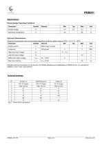
Recommended Operating Conditions
Open the catalog to page 2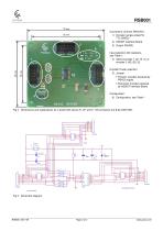
RSB001 Connectors, all 8-pin DIN41651: 1) Encoder (single ended 5V TTL/CMOS) 2) ASSIST Interface Board 3) Output (RS422) Input selection (0Ω resistors), see Table 1: 4) Select encoder 1 (A1, B, I1) or encoder 2 (A2, B2, I2) Encoder Power selection: 5) Jumper • Present: encoder powered by RS422 supply • Removed: encoder powered by ASSIST Interface Board 3 Configuration: 6) Configuration, see Table 1 Fig 4 Dimensions and explanations for a board with inputs A1, B1 and I1. All connectors are 8-pin DIN41651.
Open the catalog to page 3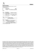
Ordering information RS422 Interface Board including flat cable for connection to ASSIST Interface Board. Code: RSB001-ABC A Input selection Table 1 B Output selection Table 2 Table 1: . Input selection © Copyright 2019 POSIC. All rights reserved. No part of this document may be reproduced without the prior written consent of POSIC. Products and companies mentioned in this document may be trademarks or registered trademarks of their respective owners. Information in this document is believed to be accurate and reliable and may be changed without notice. No responsibility is assumed by POSIC for...
Open the catalog to page 4All POSIC catalogs and technical brochures
 RSB001 RS422 Interface Board
4 Pages


Archived catalogs


- Angular encoder
- Incremental encoder
- Incremental rotary encoder
- Absolute rotary encoder
- Hollow-shaft rotary encoder
- Magnetic rotary encoder
- Industrial rotary encoder
- Compact rotary encoder
- Linear encoder
- Single-turn rotary encoder
- Ultra-rugged rotary encoder
- SSI angular encoder
- Digital rotary encoder
- High-resolution rotary encoder
- Incremental linear encoder
- Mechanical rotary encoder
- Miniature rotary encoder
- Magnetic linear encoder
- RS-422 rotary encoder
- Motor rotary encoder