PRB018 Programming Board for POSIC SMD encoders
1 /2Pages

PRB018 Programming Board for POSIC SMD encoders
1 /2Pages
Catalog excerpts

PRB018 Programming Board for POSIC SMD encoders BOARD I Description The Programming Board is intended for OTP-programming of POSIC’s 18-pin SMD encoders IT5602 and AP5603 prior to soldering. It is compatible to the Interface Board of the Evaluation and Programming Tool EPT002. Fig 1 shows how to connect the Programming Board to the ASSIST Interface Board. Fig 2 shows the opened socket containing an 18-pin encoder. To open the socket, the top side of the black lever must be pushed towards the center of the socket. Align the 18-pin encoder in the socket: - The solder side* (large copper pads) must be facing down. - The sensing side* (small copper pads) must be facing up. - The round copper mark must be at the upper right side in Error! Reference source not found.. In the socket, this corner has a larger recess/indent than the other 3 corners * See IT5602 or AP5603 datasheet Fig 3. Fig 3 shows the dimensions of the Programming Board and provides the explanations for the three jumpers. Please note that jumpers J8 and J9 (4 and 5 in Fig 3) must be set/removed according to the type of encoder (IT5602 or AP5602). Copper mark on package msiFD Fig 1 Programming Board (1) connected to ASSIST Interface Board (2), which is connected via USB cable (3) to PC with ASSIST software. Fig 2 Programming Board, socket with lid open. Ordering information PRB018 Programming board with socket for 18-pin encoders IT5602 and AP5603 including flat cable for connection to ASSIST Interface Board.
Open the catalog to page 1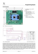
Programming Board 1) 8-pin DIN41651 connector to ASSIST Interface Board 3) Encoder Power jumper J7 • Present: encoder powered via ASSIST Interface Board connector • Removed: encoder not powered (can be powered via jumper-pin) 4) Jumper J8 must be removed 5) Jumper J9: • Present for operation with IT5602 • Removed for operation with AP5603 ENCODER POWER Fig 6 Pinout connectors J1, J2. © Copyright 2018 POSIC. All rights reserved. No part of this document may be reproduced without the prior written consent of POSIC. Products and companies mentioned in this document may be trademarks or registered...
Open the catalog to page 2All POSIC catalogs and technical brochures
 RSB001 RS422 Interface Board
4 Pages
 RSB001 - RS-4022 Driver
4 Pages


Archived catalogs


- Angular encoder
- Incremental encoder
- Incremental rotary encoder
- Absolute rotary encoder
- Hollow-shaft rotary encoder
- Magnetic rotary encoder
- Industrial rotary encoder
- Compact rotary encoder
- Linear encoder
- Single-turn rotary encoder
- Ultra-rugged rotary encoder
- SSI angular encoder
- Digital rotary encoder
- High-resolution rotary encoder
- Incremental linear encoder
- Mechanical rotary encoder
- Miniature rotary encoder
- Magnetic linear encoder
- RS-422 rotary encoder
- Motor rotary encoder