Catalog excerpts

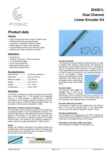
ID4501L Dual Channel Linear Encoder Kit Product data Features • • • • • • Highly miniaturized linear encoder in SMD-format Differential inductive sensing principle Insensitive to magnetic interference fields Robust against oil, water, dust, particles Programmable resolution and maximum speed Optional with cable, connector and holder Direct drives Industrial / laboratory / office automation X-Y and rotating stages Pick & Place equipment High-speed motion control Mechatronics applications Encoder assembly The encoder can be assembled by reflow soldering on a rigid or flexible PCB. Optimum performances are obtained by following the recommended schematic (Fig. 5) and footprint (Fig. 6). In particular, there should be no copper traces or metal objects behind the encoder up to a distance of 3 mm in order to avoid any influence on the measured position. If this is not possible, a blank copper layer behind the encoder (rear-side of the PCB) may be envisaged and/or a linearization using the on-chip look-up table (LUT). Description The ID4501L incremental encoder kit consists of an encoder and a linear scale (Fig. 1). The encoder is an integrated circuit in a PCB housing in SMD-format. It provides incremental A and B output signals in quadrature (Fig. 2). The linear scale is a PCB with passive copper strips. The orientation of the encoder is selected in Table 1. Resolution, maximum speed and airgap The resolution and the maximum speed of the encoder are user-programmable or can be programmed ex-factory. The resolution depends on a filter setting that limits the maximum speed of the encoder vs. the scale. The resolution also depends on the maximum distance between the encoder and the scale. The resolution and maximum speed for a certain maximum air-gap are selected in Tables 2 and 3. Scales Scales with different lengths (Fig. 4) are selected in Table 5. Each scale has a backside adhesive layer and may be mounted on any substrate, using a 0.2 mm high alignment edge for correct positioning in front of the encoder. Encoder holder The encoder holder type A is available (Fig. 7) and can be selected in Table 6. It includes the encoder and the external components according to the recommended schematic (Fig. 5). The encoder holder can be mounted on any substrate using 4 screw holes. Encoder cable and connector The encoder on holder can be supplied with a flat cable of pitch 1.27 mm and a connector (Fig. 7). The cable length and the connector type are selected in Tables 7 and 8. Encoder programming The Evaluation and Programming Tool (EPT) including an interface board and the ASSIST software is available for the linearization and programming of the encoder. 3D models of encoder, holder and scales STEP models are available on www.posic.com. Alignment edge Scale Metallic or non-metallic substrate
Open the catalog to page 1
ID4501L Specifications Recommended Operating Conditions Parameter Operating Temperature Supply voltage Lateral tolerance scale Airgap tolerance Electrical Characteristics Electrical characteristics over recommended operating conditions, typical values at VDD = 5.0 V, TA = 25°C. Parameter Supply current Maximum output frequency High level output voltage* Low level output voltage* Rise time, fall time If A is pulled up and B pulled down during power-up, the encoder enters into a test mode with a 50 kHz square wave on all outputs. Encoding Characteristics Encoding characteristics over...
Open the catalog to page 2
Index (multiple) Internal supply Internal supply Encoder dimensions (mm) and pin-out. The “Encoder center” must be centered with respect to the scale (see Fig. 4). Fig. 4 Scales TPLS04-026 (top and middle) and TPLS05-205 (bottom). All dimensions in mm. Period-length is 1.28 mm. Both scales have backside adhesive. Scale thickness includes adhesive, but not the release liner. The special periods at the left and right ends of the scale are intended for another encoder and should not be used with the ID4501. Fig. 5 Recommended schematic. The supply filter capacitor should be 1µF or more. The...
Open the catalog to page 3
ID4501L Ordering information Ordering code: ID4501L-ABBCCD-EEEEE-F-GGG-HH A Orientation Table 1 BB Maximum speed Table 2 CC Resolution Table 3 D Look-Up Table Table 4 EEEEE Linear scale Table 5 F Encoder holder Table 6 GGG Cable Table 7 HH Connector Table 8 Table 1: A 0 3 4 5 6 Orientation. Arrows indicate direction of movement of the scale with rising edge A prior to B. Orientation Not progr. 0° 90° 180° 270° Resolution Resolution Look-Up Table (LUT) Look-Up Table programmed in OTP Not programmed LUT according to scale, to be specified Custom LUT, to be specified Default LUT (no scale...
Open the catalog to page 4All POSIC catalogs and technical brochures
-
 RSB001 RS422 Interface Board
4 Pages
-
 RSB001 - RS-4022 Driver
4 Pages