

ID1102G Dual Channel Gearwheel Encoder Module

ID1102G Dual Channel Gearwheel Encoder Module
The ID1102G is a dual-channel gearwheel encoder kit featuring a highly miniaturized design and differential inductive sensing principle. It is robust against magnetic interference, oil, water, dust, and particles. The encoder is programmable for resolution and maximum speed, and it can be optionally equipped with a cable, connector, and holder.
Applications
This encoder is suitable for speed and position control in high-speed spindles, industrial automation, milling, grinding, cutting spindles, rotating equipment, high-speed motion control, and mechatronics applications.
Key Specifications
- Output format: A and B in quadrature
- Interpolation: Binary from x2 to x16,384 per tooth
- Input frequency: 0 – 25 kHz
- Output frequency: 0 – 1 MHz
- Airgap: Up to 0.6 mm
- Supply: 5 V, 10 mA
- Temperature range: -20 to 100°C
- Gear material: Ferromagnetic steel
Specifications
Recommended Operating Conditions
- Supply voltage: 4.5 to 5.5 V
- Operating temperature: -20 to 100°C
- Airgap: 0.2 mm
- Lateral tolerance: 0.5 mm
- Airgap tolerance: 0.1 mm
Electrical Characteristics
- Supply current: 8 to 15 mA
- Maximum output frequency: 0.8 to 1.2 MHz
- High level output voltage: VDD–0.5 V
- Low level output voltage: 0.5 V
- Rise and fall time: 20 ns
Encoding Characteristics
- Pulse width error: 10 to 50 °e
- State width error: 10 to 60 °e
- Phase shift error: 10 to 45 °e
Programming and Customization
The encoder can be programmed using the Evaluation and Programming Tool (EPT) with an interface board and ASSIST software. A Look-Up Table (LUT) can be programmed for linearization, either in volatile or non-volatile memory.
Ordering Information
The ordering code includes options for orientation, maximum speed, resolution, LUT, gear, encoder holder, cable, and connector. Various tables provide detailed options for each component.
Additional Information
3D models of the encoder, holders, and scales are available on the manufacturer's website. The document includes technical drawings and connector pin descriptions.
Catalog excerpts

ID1102G Dual Channel Gearwheel Encoder Kit Product data Features • Highly miniaturized gear encoder • Differential inductive sensing principle • Insensitive to magnetic interference fields • Robust against oil, water, dust, particles • Programmable resolution and maximum speed • Optional with cable, connector and holder Applications • Speed and position control in high-speed spindles • Industrial / laboratory / office automation • Milling, grinding and cutting spindles • Rotating equipment • High-speed motion control • Mechatronics applications Key Specifications Encoder holders Different encoder holder options are available and can be selected in Table 6. The encoder holder type A (Fig. 5) may be mounted on any substrate using 4 screw-holes. It has a strain relief for the cable. Metallic or non-metallic substrate Description The ID1102G incremental encoder kit consists of an encoder and a gearwheel (Fig. 1). The encoder is an integrated circuit in a PCB housing. It provides incremental A and B output signals in quadrature (Fig. 2). The gearwheel is in ferromagnetic steel and has a module 0.5. The orientation of the encoder is selected in Table 1. Resolution, maximum speed and airgap The resolution and the maximum speed of the encoder are user-programmable or can be programmed ex-factory. The resolution depends on a filter setting that limits the maximum speed of the encoder vs. the gearwheel. The resolution also depends on the maximum distance between the encoder and the gear. The resolution and maximum speed for a certain maximum air-gap are selected in Tables 2 and 3. Gearwheels Gearwheels should be made of ferromagnetic steel and have a module 0.5. Gearwheels with 12 up to 120 teeth are available and can be selected in Table 5. The encoder holder type B (Fig. 3) may be mounted on any substrate. Use half-holes on encoder PCB housing and alignment pins for accurate positioning. The encoder without holder may be mounted on non-metallic substrates. Use half-holes on encoder housing and alignment pins for accurate positioning. Encoder cable and connector The encoder can be supplied with a flat cable of pitch 1.27 mm and a connector (Fig. 6). The cable length and the connector type are selected in Tables 7 and 8. Encoder programming The Evaluation and Programming Tool (EPT) including an interface board and the ASSIST software is available for the linearization and programming of the encoder. 3D models of encoder, holders and scales STEP models available on www.posic.com.
Open the catalog to page 1
Recommended Operating Conditions Linearity For high-resolution high-precision applications, it is possible to linearize the encoder by means of a Look-Up Table (LUT) that is located inside the encoder. The LUT can be programmed in volatile or in non-volatile memory by means of the Evaluation and Programming Tool (EPT) or it can be pre-programmed by ex-factory. The LUT option is selected in Table 4. 0 = Phase P = Pulse width <-> Definitions Airgap Cycle °e Phase shift O Pulse width P State width S Fig. 2 Encoder output signals A and B in quadrature. Distance between encoder and gear in Z-direction....
Open the catalog to page 2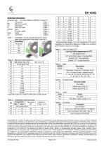
BB Maximum speed Table 2 D Look-Up Table Table 4 EEEEE Gear Table 5 F Encoder holder Table 6 Table 1: Orientation. Arrows indicate direction of move ment of the scale with rising edge A prior to B. Table 2: . Maximum input frequency * Recommended airgap = 0.2 mm. Sequence of A and B transitions is correct up to Maximum Airgap, but encoding specifications may be out of range. Lower Max input freq. leads to lower jitter of A/B outputs. Table 4: . Look-Up Table (LUT) © Copyright 2017 POSIC. All rights reserved. No part of this document may be reproduced without the prior written consent of POSIC....
Open the catalog to page 4All POSIC catalogs and technical brochures
 RSB001 RS422 Interface Board
4 Pages
 RSB001 - RS-4022 Driver
4 Pages


Archived catalogs


- Angular encoder
- Incremental rotary encoder
- Absolute rotary encoder
- Industrial rotary encoder
- Hollow-shaft rotary encoder
- Magnetic rotary encoder
- Compact rotary encoder
- DC rotary encoder
- Linear encoder
- Single-turn rotary encoder
- Ultra-rugged rotary encoder
- High-resolution rotary encoder
- SSI angular encoder
- Digital rotary encoder
- 5VDC rotary encoder
- Incremental linear encoder
- Mechanical rotary encoder
- Miniature rotary encoder
- RS-422 rotary encoder