ID1102C Dual ChannelRotary Encoder Kit
1 /4Pages

ID1102C Dual ChannelRotary Encoder Kit
1 /4Pages
Catalog excerpts

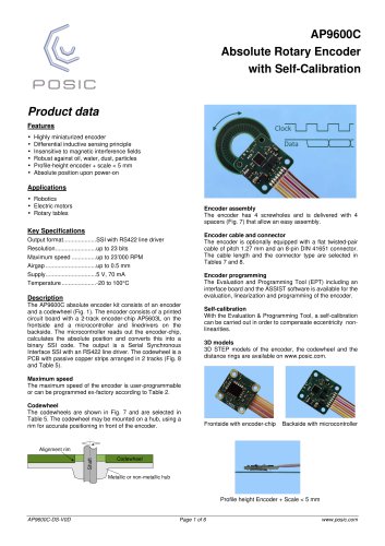
ID1102C Dual Channel Rotary Encoder Kit Product data Features • • • • • • Highly miniaturized encoder Differential inductive sensing principle Insensitive to magnetic interference fields Robust against oil, water, dust, particles Programmable resolution and maximum speed Optional with cable, connector and holder Brushed and brushless motors Industrial and laboratory automation Rotary stages Robotics, assembly equipment High-speed motion control Encoder holders Different encoder holder options are available and can be selected in Table 6. The encoder holder type A (Fig. 5) may be mounted on any substrate using 4 screw-holes. It has a strain relief for the cable. The encoder holder type B (Fig. 3) may be mounted on any substrate. Use half-holes on encoder PCB housing and alignment pins for accurate positioning. Description The ID1101C incremental encoder kit consists of an encoder and a codewheel (Fig. 1). The encoder is an integrated circuit in a PCB housing. It provides incremental A and B output signals in quadrature (Fig. 2). The codewheel is a PCB with passive copper strips. The orientation of the encoder is selected in Table 1. Resolution, maximum speed and airgap The resolution and the maximum speed of the encoder are programmed ex-factory. The resolution depends on a filter setting that limits the maximum speed of the encoder vs. the codewheel. The resolution also depends on the maximum distance between the encoder and the codewheel. The resolution and maximum speed for a certain maximum airgap are selected in Tables 2 and 3. Codewheel The codewheels are shown in Fig. 4 and are selected in Table 5. The codewheel may be mounted on a hub, using a rim for accurate positioning in front of the encoder. The encoder without holder may be mounted on nonmetallic substrates. Use half-holes on encoder housing and alignment pins for accurate positioning. Encoder cable and connector The encoder can be supplied with a flat cable of pitch 1.27 mm and a connector (Fig. 6). The cable length and the connector type are selected in Tables 7 and 8. Encoder programming The Evaluation and Programming Tool (EPT) including an interface board and the ASSIST software is available for the linearization and programming of the encoder. 3D models of encoder, holders and scales STEP models available on www.posic.com. ID1102C-DS-V3A
Open the catalog to page 1
ID1102C Specifications Recommended Operating Conditions Parameter Operating Temperature Supply voltage Radial play and eccentricity Airgap tolerance Electrical Characteristics Electrical characteristics over recommended operating conditions, typical values at VDD = 5.0 V, TA = 25°C. Parameter Maximum output frequency Supply current High level output voltage* Low level output voltage* Rise time, fall time If A is pulled up and B pulled down during power-up, the encoder enters into a test mode with a 50 kHz square wave on all outputs. Encoding Characteristics Encoding characteristics over recommended...
Open the catalog to page 2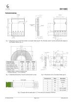
Dimensions (mm) of ID1102 encoder on encoder-holder type B. The “Encoder center” must be centered with respect to the Readout Radius (Fig. 4). Codewheel type * Readout Radius = position of encoder center ** Thickness tolerance +/- 10% of thickness Fig. 4 Codewheel dimensions. Only the external track is used. Fig. 5 Dimensions (mm) of encoder-holder type A. Index (multiple) Fig. 6 Encoder with flat cable (pitch 1.27 mm) and 6-pin connector DIN41651.
Open the catalog to page 3
ID1102C Ordering information Ordering code: ID1102C-ABBCCD-EEEEE-F-GGG-HH A Orientation Table 1 BB Maximum speed Table 2 CC Resolution Table 3 D Look-Up Table Table 4 EEEEE Codewheel Table 5 F Encoder holder Table 6 GGG Cable Table 7 HH Connector Table 8 Table 1: A 0 3 4 5 6 Orientation. Arrows indicate direction of movement of the scale with rising edge A prior to B. Orientation Not progr. 0° 90° 180° 270° Look-Up Table (LUT) Look-Up Table programmed in OTP Not programmed LUT according to codewheel, to be specified Custom LUT, to be specified Default LUT, no codewheel specified Table 5: Codewheel...
Open the catalog to page 4All POSIC catalogs and technical brochures
 RSB001 RS422 Interface Board
4 Pages
 RSB001 - RS-4022 Driver
4 Pages


Archived catalogs


- Incremental rotary encoder
- Absolute rotary encoder
- Hollow-shaft rotary encoder
- Magnetic rotary encoder
- Industrial rotary encoder
- Compact rotary encoder
- Linear encoder
- Single-turn rotary encoder
- Ultra-rugged rotary encoder
- SSI angular encoder
- Digital rotary encoder
- High-resolution rotary encoder
- Incremental linear encoder
- Mechanical rotary encoder
- Miniature rotary encoder
- Magnetic linear encoder
- RS-422 rotary encoder
- Motor rotary encoder