EPT002 Evaluation and Programming Tool
1 /2Pages

EPT002 Evaluation and Programming Tool
1 /2Pages
Catalog excerpts
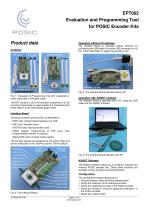
EPT002 Evaluation and Programming Tool for POSIC Encoder Kits Product data Operation without PC/software The Interface Board is operated without software by connecting the USB-cable to a mains-USB converter or to a PC. Press “Start/Stop” to toggle the encoder on/off. Codewheel or linear scale Interface Board Encoder signals Gear Fig. 3: The Interface Board operated without PC Fig. 1: Evaluation & Programming Tool with codewheel or linear scale (left) or with gear (right). The EPT contains a 28.2 mm diameter codewheel or a 100 mm long 2-track scale or a gear module 0.5. Codewheel and linear scale fit in the white plastic target holder. Operation with ASSIST software The Interface Board is operated with a PC using the USB cable and the ASSIST software. Interface Board The board contains several LEDs as listed below: - PWR (red): Interface Board powered via USB - ENC (red): Encoder active - SYSTEM (red): Microcontroller active - PROG (yellow): Programming of OTP (One Time Programmable) memory is ongoing - Signal LEDs (red): encoder output signals The encoder signals are visualized by the signal LEDs and can be measured on the TestPins and the Terminal Block. PWR LED ENC LED POSIC Encoder Reference Encoder Fig. 4: The Interface Board operated with PC USB Signal LEDs ASSIST Software Start/Stop button The ASSIST software allows you to configure, evaluate and linearize POSIC encoder kits. These three functions are available in three windows as explained below. Reset button Terminal block Signal TestPins Microcontroller Ground connection Target holder Linear scale Configuration The configuration window allows you to: • Choose between rotary and linear measurement • Define the resolution of the reference encoder • Define the codewheel or scale of the POSIC encoder • Select the resolution, maximum speed and orientation of the POSIC encoder • Select the LookUp Table
Open the catalog to page 1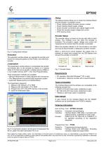
EPT002 Debug The Debug window allows you to check the Interface Board and the encoder if a problem occurs: • Check Interface Board firmware revision number • Check Interface Board supply voltage • Check encoder connections (all outputs toggle on/off) • Check the encoder supply voltage and current • OTP memory dump Encoder Status The encoder status is shown at the top right side of each window. The indicator turns red when the encoder is activated. The encoder’s supply voltage and current are measured at the moment that the encoder is activated. When the encoder-indicator is off, the encoder is...
Open the catalog to page 2All POSIC catalogs and technical brochures
 RSB001 RS422 Interface Board
4 Pages
 RSB001 - RS-4022 Driver
4 Pages


Archived catalogs


- Angular encoder
- Incremental encoder
- Incremental rotary encoder
- Absolute rotary encoder
- Hollow-shaft rotary encoder
- Magnetic rotary encoder
- Industrial rotary encoder
- Compact rotary encoder
- Linear encoder
- Single-turn rotary encoder
- Ultra-rugged rotary encoder
- SSI angular encoder
- Digital rotary encoder
- High-resolution rotary encoder
- Incremental linear encoder
- Mechanical rotary encoder
- Miniature rotary encoder
- Magnetic linear encoder
- RS-422 rotary encoder
- Motor rotary encoder