Absolute Inductive Rotary Encoder Kit AP9600C
1 /6Pages
Absolute Inductive Rotary Encoder Kit AP9600C
1 /6Pages
Catalog excerpts
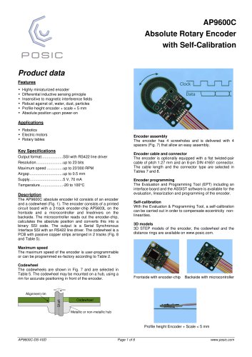
AP9600C Absolute Rotary Encoder with Self-Calibration Product data Features • • • • • • Highly miniaturized encoder Differential inductive sensing principle Insensitive to magnetic interference fields Robust against oil, water, dust, particles Profile-height encoder + scale < 5 mm Absolute position upon power-on Applications • Robotics • Electric motors • Rotary tables Encoder assembly The encoder has 4 screwholes and is delivered with 4 spacers (Fig. 7) that allow an easy assembly. Encoder cable and connector The encoder is optionally equipped with a flat twisted-pair cable of pitch 1.27 mm and an 8-pin DIN 41651 connector. The cable length and the connector type are selected in Tables 7 and 8. Encoder programming The Evaluation and Programming Tool (EPT) including an interface board and the ASSIST software is available for the evaluation, linearization and programming of the encoder. Description The AP9600C absolute encoder kit consists of an encoder and a codewheel (Fig. 1). The encoder consists of a printed circuit board with a 2-track encoder-chip AP5603L on the frontside and a microcontroller and linedrivers on the backside. The microcontroller reads out the encoder-chip, calculates the absolute position and converts this into a binary SSI code. The output is a Serial Synchronous Interface SSI with an RS422 line driver. The codewheel is a PCB with passive copper strips arranged in 2 tracks (Fig. 8 and Table 5). Self-calibration With the Evaluation & Programming Tool, a self-calibration can be carried out in order to compensate eccentricity nonlinearities. 3D models 3D STEP models of the encoder, the codewheel and the distance rings are available on www.posic.com. Maximum speed The maximum speed of the encoder is user-programmable or can be programmed ex-factory according to Table 2. Codewheel The codewheels are shown in Fig. 7 and are selected in Table 5. The codewheel may be mounted on a hub, using a rim for accurate positioning in front of the encoder. Frontside with encoder-chip Backside with microcontroller Profile height Encoder + Scale < 5 mm
Open the catalog to page 1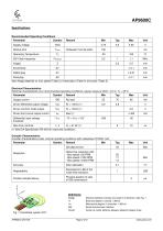
Recommended Operating Conditions Distance between encoder and scale in Z-direction. See Fig. 1. Electrical degree (1 period = 360°e) Mechanical degree (1 revolution = 360°m) Serial Synchronous Interface Center-to-center distance between adjacent copper strips
Open the catalog to page 2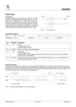
Connections The SSI (Synchronous Serial Interface) uses fully RS-422 compliant 5V differential transmission channels (Fig. 2). The clock input is terminated with a 120Q resistor inside the encoder. For reliable transmission on long cables, the user has to terminate the data lines on the controller side with a resistor corresponding to the characteristic impedance of the used cable. The balanced characteristic impedance of a .05” AWG28 7/36 twisted pair flat cable is generally in the range of 120Q. Transmission protocol A single data frame consist of 31 bits (Fig. 3). On the leading clock edge...
Open the catalog to page 3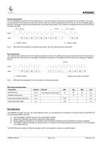
AP9600C Partial transmission It is not mandatory to read the full 31 bit data frame. If only the first part of the frame is of interest for the controller, it can stop the transmission of the frame by holding the clock line high for a period exceeding the clock time-out. At the next falling edge of the clock, the position data will be refreshed and a new data frame started. Fig. 4 shows an example where only the first 8 bit of the frame are read. SSI frame timing diagram for partial transmission, only the initial 8 bits are transmitted. Re-transmission The encoder also implements the SSI multiple...
Open the catalog to page 4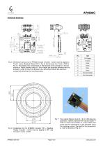
Fig. 7 Four plastic distance rings of 1.6 mm thickness are optionally (Table 6) delivered with each encoder in order to mount the encoder on a flat surface and avoid that the components on the backside touch the mounting-surface. The height of the components Fig. 8 Codewheel for the AP9600C encoder. RR = Readout is 1.45 mm maximum (Fig. 6). Radius. Encoder 1 center must be aligned to RR1 and Encoder 2 center to RR2.
Open the catalog to page 5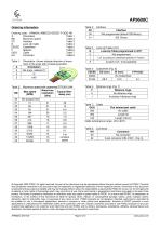
BB Maximum speed Table 2 D Look-Up Table Table 4 EEEEE Codewheel Table 5 © Copyright 2025 POSIC. All rights reserved. No part of this document may be reproduced without the prior written consent of POSIC. Products and companies mentioned in this document may be trademarks or registered trademarks of their respective owners. Information in this document is believed to be accurate and reliable and may be changed without notice. No responsibility is assumed by POSIC for its use, nor for infringements of patents or other rights of third parties which may result from its use. Some commercial or geographical...
Open the catalog to page 6All POSIC catalogs and technical brochures
 RSB001 RS422 Interface Board
4 Pages
 RSB001 - RS-4022 Driver
4 Pages


Archived catalogs


- Incremental encoder
- Incremental rotary encoder
- Absolute rotary encoder
- Hollow-shaft rotary encoder
- Magnetic rotary encoder
- Industrial rotary encoder
- Compact rotary encoder
- Linear encoder
- Single-turn rotary encoder
- Ultra-rugged rotary encoder
- SSI angular encoder
- Digital rotary encoder
- High-resolution rotary encoder
- Incremental linear encoder
- Mechanical rotary encoder
- Miniature rotary encoder
- Magnetic linear encoder
- RS-422 rotary encoder
- Motor rotary encoder