ZRR6
1 /8Pages

ZRR6
1 /8Pages
Catalog excerpts

Pressure reducing valve, pilot operated, sandwich plate type UZRR6 APPLICATION The pressure reducing valve type UZRR6… is used for reducing pressure in hydraulic systems. subplate side The valve consists of pilot valve and main valve. The reduced pressure acts on the lower face of main spool (1), and through nozzle (2) also on the upper face and through nozzle (3) on pilot valve poppet (4). In rest position the pressure on both sides of the main spool (1) is identical. Spring (5) maintains the spool in initial (open) position. Lines P and P1 (A1 to A, B1 to B) are A1 interconnected. When the pressure attains the value determined by the tension of spring (6), the pilot valve (4) opens and oil flows through nozzle (2). A pressure drop is created across the nozzle, which acts on the upper and lower faces of spool (1) and moves it causing throttling of flow from P to P1 (A1 to A, B1 to B). A1 Unrestricted flow in opposite direction from A to A1 (B B to B1 is effected through check valve (7) - design with B1) check valve UZRR6…AZ (UZRR6…BZ AZ; BZ). AZ BZ
Open the catalog to page 1
TECHNICAL DATA Hydraulic fluid Req filtrat ati Required f iltr ation Recommended filtration Nominal fluid viscosity Viscosity range Fluid temperature range (in a tank) Ambient temperature range ati Maximum oper ating pres sure imum operat press Maximum set press ure imum Pressure co necti Press ure at inlet c onnection Pressure co necti Press ure at outlet c onnect ion Settable pressure range Maximum flow imum fl Weight SCHEMES Hydraulic schemes of valves type UZRR6... UZ version UZRR6...P... component side component side component side subplate side subplate side subplate side component side...
Open the catalog to page 2
OVERALL AND CONNECTION DIMENSIONS versi 6...P... vers ion UZRR6... P... component side subplate side 1 - Seal o-ring 9,25 x 1,78 - 4 pcs/kit (P, T, A, B) 9,25 1,7 P 2 - Mounting holes configuration of a subplate in accordance with the standards listed below: • CETOP RP 121H - symbol CETOP 4.2-4-03 03 (nominal size CETOP 03 03) • ISO 4401 - symbol ISO 4401 03 4401-03 03-02-0-94 fixing screws M5 x L* - 10.9 - 4 pcs/kit in accordance with PN - EN ISO 4762 tightening torque Md = 9 Nm 3 - Required surface finish of a subplate NOTE: (*) - Required length of the screws L is related to type and the number...
Open the catalog to page 3
OVERALL AND CONNECTION DIMENSIONS versi UZ RR6 .AZ vers ions: UZRR6...A... ; UZRR6...AZ... component side subplate side 1 - Seal o-ring 9,25 x 1,78 - 4 pcs/kit (P, T, A, B) 9,25 1,7 P 2 - Check valve in line A - A1 - only for version UZRR6…AZ AZ… AZ 3 - Mounting holes configuration of a subplate in accordance with the standards listed below: • CETOP RP 121H - symbol CETOP 4.2-4-03 03 (nominal size CETOP 03 03) • ISO 4401 - symbol ISO 4401 03 4401-03 03-02-0-94 fixing screws M5 x L* - 10.9 - 4 pcs/kit in accordance with PN - EN ISO 4762 tightening torque Md = 9 Nm 4 - Required surface finish of...
Open the catalog to page 4
OVERALL AND CONNECTION DIMENSIONS versi UZ RR6 .BZ vers ions: UZRR6...B... ; UZRR6...BZ... component side subplate side 1 - Seal o-ring 9,25 x 1,78 - 4 pcs/kit (P, T, A, B) 9,25 1,7 P 2 - Check valve in line B - B1 - only for version UZRR6…BZ… B 3 - Mounting holes configuration of a subplate in accordance with the standards listed below: • CETOP RP 121H - symbol CETOP 4.2-4-03 03 (nominal size CETOP 03 03) • ISO 4401 - symbol ISO 4401 03 4401-03 03-02-0-94 fixing screws M5 x L* - 10.9 - 4 pcs/kit in accordance with PN - EN ISO 4762 tightening torque Md = 9 Nm 4 - Required surface finish of a...
Open the catalog to page 5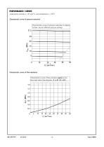
measured at viscosity ν = 41 mm 2/s and temperature t = 50 C urves pressure reduct ucti Characteristic c urves of press ure red uct ion aracteristic cur acter Characteristic curves of pressure reduction in relation to flow rate for different pressure settings urves res ance Characterist ic c urves of f low resistance aracteristic cur acter Characteristic curves of flow resistance ∆p(Q) across the check valve, flow direction: A → A1 (B → B1) 1,4 1,4 1,2 1,2
Open the catalog to page 6
Series number (30-39) - connection and installation dimensions unchanged = 3X Sellable pressure range Adjustment element set screw with internal hexagon_=2 Connection (according to schemes on page 2) Reduction in line A + check valve = AZ Reduction in line B + check valve = BZ NBR (for fluids on mineral oil base) = no code FKM (for fluids on phosphate ester base) =V Further requirements in clear text (to be agreed with the manufacturer) The pressure reducing valve should be ordered according to the above coding. The symbols in bold are the preferred versions available in short delivery time.
Open the catalog to page 7
SUBPLATES AND FIXING SCREWS Subplates must be ordered according to catalogue sheet WK 496 480. Subplate symbols: G 341/01 - threaded connections G 1/4 G 342/01 - threaded connections G 3/8 G 502/01 - threaded connections G 1/2 G 341/02 - threaded connections M14 x 1,5 G 342/02 - threaded connections M16 x 1,5 Subplates and screws fixing the pressure reducing valve M5 x L*- 10,9 - 4 pcs/kit in accordance with 0,9 PN - EN ISO 4762 must be ordered separately. Tightening torque Md = 9 Nm NOTES: (*) - Required length of the screws L is related to type and the number of hydraulic components sandwich...
Open the catalog to page 8All PONAR S.A. catalogs and technical brochures
 PRESSURE SWITCH TYPE USPH 1
4 Pages
 MK series
4 Pages
 MG series
4 Pages
 UZKB 6
6 Pages
 DZ5DP
DZ5DP6 Pages
 DR5DP
DR5DP6 Pages
 UZPD30
8 Pages
 Reverse valve type URJP10
4 Pages
 Directional spool valve type WE6
16 Pages
 General Catalogue
1200 Pages
 Catalogue products
20 Pages


Archived catalogs
 Blocks
4 Pages
 Hydraulic Systems
41 Pages
 Hydraulic Cylinders
11 Pages

- Control valve
- Cylinder
- Electrically operated valve
- Regulating valve
- On/off valve
- Flap valve
- NC solenoid valve
- 2-way solenoid valve
- Direct-operated solenoid valve
- Directional control valve
- Double-acting cylinder
- Hydraulic pump
- Hydraulic cylinder
- Butterfly valve
- Heat exchanger unit
- Pressure switch
- Oil valve
- Hydraulic valve