
- Catalogs
- PONAR S.A.
- MG series

MG series

MG series
Application:
Throttle valves type MG are designed to regulate fluid flow in hydraulic systems. They are suitable for systems where the working resistance is constant or where speed changes due to load variations are not critical. These valves are mounted directly in-line and can be positioned in any orientation.
Description of Operation:
The valve operates by adjusting the fluid flow through a throttle point formed between the housing and an adjustable sleeve. The flow can be controlled by rotating the sleeve, which changes the circular section at the throttle point. The valve can throttle fluid in both directions. It is important to install the valve by securing the hexagon of the housing and not to adjust it under pressure.
Technical Data:
- Hydraulic Fluid: Mineral oil
- Filtration: Up to 16 µm, recommended up to 10 µm
- Nominal Fluid Viscosity: 37 mm²/s at 55°C
- Viscosity Range: 2.8 to 380 mm²/s
- Fluid Temperature Range: -20°C to +70°C
- Maximum Operating Pressure: 31.5 MPa
Overall Dimensions:
Dimensions vary by size, with sizes ranging from 6 to 30. Each size has specific dimensions for diameter, length, and weight.
Performance Curves:
The document includes performance curves showing the relationship between flow rate (Q) and pressure drop (Δp) for different valve sizes.
Ordering Information:
Throttle valves should be ordered using a specific coding system. The preferred versions are highlighted for quick delivery. The coding includes mounting type, series number, sealing type, and nominal size.
Contact Information:
PONAR Wadowice S.A., ul. Wojska Polskiego 29, 34-100 Wadowice, Poland. Phone: +48 33 488 29 00, Fax: +48 33 488 21 03, Website: www.ponar-wadowice.pl
Catalog excerpts

THROTTLE VALVE TYPE MG Size 6 through 30 up to 31,5 MPa up to 400dm3/min APPLICATION Throttle valves type MG serve to regulate (restrict) the fluid flow, which depends on the pressure drop at the throttle position and the fluid viscosity. The valves may be used in hydraulic systems, when working resistance is constant or change in speed at changing load is of no importance. The valves are for direct in-line mounting in any position by means of couplings. 4 Fluid gets at the throttle point 3 formed between the housing and the adjustable sleeve 4 through side bores 1 in the housing 2. By rotating the sleeve, the circular section at the throttle point may be steplessly changed. The valve throttles in both directions. Caution: Caution: hold The valve install in hydraulic system to take hold on 2. hexagon of housing item 2. 4. It isn’t to allow for turn up the valve by nut item 4. Do not adjust under pressure.
Open the catalog to page 1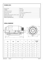
TECHNICAL DATA Hydraulic fluid Recommended filtration Nominal fluid viscosity Viscosity range Optimum working temperature (fluid in a tank) Fluid temperature range ati press Maximum oper ating pres sure imum operat OVERALL DIMENSIONS
Open the catalog to page 2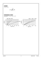
SCHEMES Graphical symbol PERFORMANCE CURVES measured meas ured at v = 41 mm 2/s and t = 50 oC
Open the catalog to page 3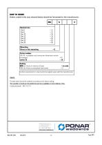
Orders coded in the way showed below should be forwarded to the manufacturer. Nominal size Direct in-line mounting Series number (10-19) - installation and connection dimensions remain NBR (for Fluids on mineral oil base) FPM (For Fluids on phosphate ester base) Further requirements in clear text (to be agreed upon with the manufacturer) Throttle valve should be ordered according to the above coding. The symbols in bold are the preferred versions available in short delivery time.
Open the catalog to page 4All PONAR S.A. catalogs and technical brochures
 PRESSURE SWITCH TYPE USPH 1
4 Pages
 MK series
4 Pages
 ZRR6
ZRR68 Pages
 UZKB 6
6 Pages
 DZ5DP
DZ5DP6 Pages
 DR5DP
DR5DP6 Pages
 UZPD30
8 Pages
 Reverse valve type URJP10
4 Pages
 Directional spool valve type WE6
16 Pages
 General Catalogue
1200 Pages
 Catalogue products
20 Pages


Archived catalogs
 Blocks
4 Pages
 Hydraulic Systems
41 Pages
 Hydraulic Cylinders
11 Pages

- Control valve
- Cylinder
- Electrically operated valve
- Regulating valve
- On/off valve
- Flap valve
- Check valve
- 2-way solenoid valve
- NC solenoid valve
- Directional control valve
- Hydraulic pump
- Direct-operated solenoid valve
- Double-acting cylinder
- Hydraulic cylinder
- Butterfly valve
- Heat exchanger unit
- Pressure switch
- Oil valve
- Hydraulic valve