Catalog excerpts

Double throttle/check valve type Z2FS6 APPLICATION Throttle/check valve type Z2FS6... is used to control Z2FS6... main flow rate (or pilot flow rate) in one direction of flow and to allow free flow in the opposite direction. The valve may be designed as double version (twin version - valve function is realized in two ports A and B) or single version (valve function is realized in one port A or B). The valve is applied to vertical stack mounting (sandwich plate) - generally is fitted between subplate and directional valve of the same nominal size and in this case is used to limit main flow rate (to control the speed of a receiver movement). For directional valves pilot operated the valve is installed as a pilot choke adjuster (to limit pilot flow rate). In this case it is fitted between the main and the pilot valve. side of a component closing the stack Hydraulic fluid from directional valve via port A (or B) flows to receiver through throttling slot (1). At the same time the fluid under operating pressure acts via line A on spring (4) loaded side of spool (2). The spool (2) is thus hold in the throttle position by both spring (4) and hydrostatic force.. Hydraulic fluid flowing back from a receiver through port B (or A) shifts the spool (2) in the direction of adjustment and allows the fluid to flow freely (the valve operates as a check valve). Throttle rate (volume of fluid flow) can be adjusted by means of adjustment screw (3). Depending on the way the valve is fitted in relation to the seal ring plate (5), throttling effect can be achieved either in the supply of a receiver (option shown on the drawing) or drain (by rotating the valve about the longitudinal horizontal axis by 180°).
Open the catalog to page 1
TECHNICAL DATA Hydraulic fluid Req filtrat ati Required f iltration Recommended filtration Nominal fluid viscosity Viscosity range Fluid temperature range (in a tank) Ambient temperature range ati press Maximum operating pres sure imum operat Crack press Cracking pres sure ac SCHEMES Hydraulic schemes of valves type Z2FS6... 2FS double version Z2FS6.../... supply throttling drain throttling side of a component closing the stack side of a component closing the stack subplate side subplate side supply throttling drain throttling side of a component closing the stack subplate side side of a...
Open the catalog to page 2
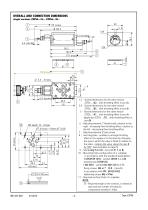
OVERALL AND CONNECTION DIMENSIONS double version Z2FS6.../... 1 1,2 - Overall dimensions for the valve version Z2FS6.../2… with throttling effect in ports A, B 2 3 - Adjusting element 1 (hand knob); rotation to the right - increasing flow throttling effect; rotation to the left - decreasing flow throttling effect 4 - Adjusting element 2 (set screw) 5 - Overall dimensions for the valve version Z2FS6.../1… with throttling effect in ports A, B 1 6 - Seal ring plate - enables to arrange throttling effect in the supply or in the drain by changing the way in which the valve is fitted in relation...
Open the catalog to page 3
OVERALL AND CONNECTION DIMENSIONS single versions: Z2FS6.../A...; Z2FS6.../B... 1 2 1,2 - Overall dimensions for the valve version Z2FS6…/A2... with throttling effect in port A A 3,4 - Overall dimensions for the valve version Z2FS6…/B2... with throttling effect in port B B 5 - Overall dimensions for the valve version Z2FS6…/A1... with throttling effect in port A A (apply also Z2FS6…/B1... with throttling effect in B port B) 6 - Adjusting element 1 (hand knob); rotation to the right - increasing flow throttling effect; rotation to the left - decreasing flow throttling effect 7 - Adjusting...
Open the catalog to page 4
measured at viscosity ν = 41 mm 2/s and temperature t = 50 C Flow resistance curve ∆p(Q) for the check valve - throttle closed Characteristic curves ∆p(Q) for the valve 2FS type Z2FS6... for various throttle settings EXAMPLES OF APPLICATION IN HYDRAULIC SYSTEM Flow throttling in the supply of the receiver (actuator) Flow throttling in the drain of the receiver (actuator) - valve fitted in rotated position by 180°
Open the catalog to page 5
HOW TO ORDER Z2FS Nominal size (NS) NS6 Series number (40-49) - connection and installation dimensions unchanged series 42 Throttling location (hydraulic schemes on page 2) throttle valves on the side of ports A and B throttle valve on the side of port A throttle valve on the side of port B Setting element hand knob set screw with internal hexagon Sealing NBR (for fluids on mineral oil base) FKM (for fluids on phosphate ester base) Further requirements in clear text (to be agreed with the manufacturer) NOTES: The throttle/check valve should be ordered according to the above coding. The...
Open the catalog to page 6All PONAR S.A. catalogs and technical brochures
-
PRESSURE SWITCH TYPE USPH 1
4 Pages
-
MK series
4 Pages
-
MG series
4 Pages
-
ZRR6
8 Pages
-
UZKB 6
6 Pages
-
DZ5DP
6 Pages
-
DR5DP
6 Pages
-
UZPD30
8 Pages
-
Reverse valve type URJP10
4 Pages
-
Directional spool valve type WE6
16 Pages
-
General Catalogue
1200 Pages
-
Catalogue products
20 Pages
Archived catalogs
-
Blocks
4 Pages
-
Hydraulic Systems
41 Pages
-
Hydraulic Cylinders
11 Pages


