
- Catalogs
- PONAR S.A.
- Directional spool valve type WEH16

Directional spool valve type WEH16

Directional spool valve type WEH16
Catalog excerpts

Directional spool valve type WEH16 electro-hydraulically operated DATA SHEET - SERVICE MANUAL Directional spool valves type WEH16... electro- hydraulically operated are intended for change in direction of fluid flow in a system and thus it allows to change direction of movement of a receiver - mostly piston rod of a cylinder or hydraulic motor as well to use functions: on and off. These directional spool valves are used for subplate mounting in any position in a hydraulic system. The directional spool valve type WEH16... is complied with the regulations of directive 2006/95/WE for the following voltages: Main bore and annular ports P, T, A, B are made in the housing (1) and connected to its subplate connection. Directional valve is switched by shifting the spool (2) into one end position. Various control functions are dependent on the spool (2) which affects the change in configuration of connections among ports P, T, A, B in the housing (1). The spool (2) is shifted from its neutral position by affecting pressure of hydraulic fluid supplied via pilot valve (A) into one chamber of caps (3). The pilot valve (A) - type WE6...12/... according to data sheet WK 499 502 is operated by means of solenoids (5). In case of failure, the pilot valve (A) may be shifted manually by means of manual overrides (6) - version ...4WEH16.../...N. The spool (2) is centered in neutral position by means of springs (7) - operated by the fluid pressure from the pilot valve (A) valves the centering is possible by means of the sleeve (8). Sealing of the directional valve to a subplate is secured by sealing rings. Sealing between mounting surface of the valve and subplate is assured by sealing
Open the catalog to page 1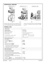
Directional spool valves may be provided with the pilot choke adjustment (10) as well as with accessories such as: spool stroke limiter (11), spool end position TECHNICAL DATA monitor (12). Accessories may be mounted depending on version of directional valve like given on pages
Open the catalog to page 2
Fluid volume required to operate the valve 3-position spring centered directional valve 3-position hydraulically centered directional valve from tf(neutral) to operated position a from 0(neutral) to operated position b from operated position a to 0(neutral) position from operated position b to 0(neutral) position 2-position directional spool valve Total time of spool shifting from neutral to 3-position spring centered directional valve 3-position hydraulically centered directional valve Total time of spool shifting from end to neutral 3-position spring centered directional valve 3-position hydraulically...
Open the catalog to page 3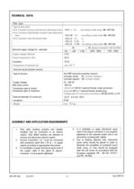
TECHNICAL DATA ASSEMBLY AND APPLICATION REQUIREMENTS 1. Only valve working properly and suitably installed may be connected to an electric system. Only skilled workers are allowed to connect and disconnect electric system. 2. Ground connection ( ^ ) must be connected with protective earth wire ( PE ^ ) in supply system according to appropriate instructions. 3. It is forbidden to apply directional spool valve if the supply cable in the gland of plug-in- connector is not properly tightened. 4. It is forbidden to apply directional spool valve if the plug-in-connector is not properly tightened to...
Open the catalog to page 4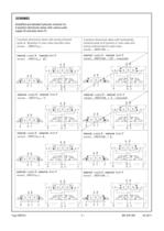
Simplified and detailed hydraulic schemes for 3-position directional valves with various pilot supply (X) and pilot drain (Y) 3-position directional valves with spring centered spool at ^position in main valve and pilot valve 3-position directional valves with hydraulically centered spool at 0 position in main valve and spring centered spool in pilot valve internal supply X; internal drain Y internal supply X; internal drain Y external supply X; internal drain Y external supply X ; internal drain Y internal supply X; external drain Y internal supply X; external drain Y external supply X ; external...
Open the catalog to page 5
Simplified and detailed hydraulic schemes for 2-position directional valves with various pilot supply (X) and pilot drain (Y) 2-position directional valves with spring positioned spool in main valve and pilot valve 2-position directional valves with hydraulically positioned spool in main valve and spring positioned spool in pilot valve internal supply X; internal drain Y internal supply X; internal drain Y external supply X; internal drain Y external supply X; internal drain Y internal supply X; external drain Y internal supply X; external drain Y external supply X ; external drain Y external...
Open the catalog to page 6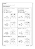
Simplified and detailed hydraulic schemes for 2-position directional valves with various pilot supply (X) and pilot drain (Y) 2-position directional valves with hydraulically positioned spool in main valve, pilot valve without return spring 2-position directional valves with hydraulically positioned spool in main valve, pilot valve without return spring, with detent internal supply X; internal drain Y internal supply X; internal drain Y external supply X; internal drain Y external supply X; internal drain Y internal supply X; external drain Y internal supply X; external drain Y external supply...
Open the catalog to page 7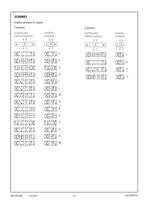
Graphic symbols for spools indirect positions indirect positions
Open the catalog to page 8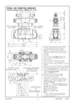
OVERALL AND CONNECTION DIMENSIONS 15 3-position standard versions ...4WEH16...7X/...S...D1... 4 6 9 2 8 5 3 15 a b 14 7 O O 11 - 2 spotfaces 6,6 - 2 holes B Y 1 10 11 12 240 O 3 -2 pins 91 220 13 110 3 34 43 96 A 25 16,5 - 4 spotfaces 11 - 4 holes 30 OO 86 (93) A B P T 69,9 L 1,5 Y B B Y A 60 80 X P T A X 1,6 34,1 50 101,6 O O O 17,5 (max) - 4 holes (P,A,B,T) 4 depth 8 - 2 holes 4 - 3 holes (X,Y,L*) M6 depth17- 2 holes M10 depth17- 4 holes 1,6 L* T A P X B Y 18,3 34,1 50 65,9 76,6 88,1 101,6 144 (min) Type WEH16 12,7 14,3 54 91 (min) 71,5 69,9 55,6 35 16 r 0,01/100 mm 0,63 17 -9- 1 - 3-position...
Open the catalog to page 9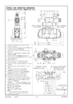
OVERALL AND CONNECTION DIMENSIONS 2-position standard versions ...4WEH16...7X/...S...D... 4 9 2 8 5 3 15 6 15 14 25 30 7 A b a 86 (93) B OO O O 16,5 - 4 spotfaces 11 - 4 holes 11 - 2 spotfaces 6,6 - 2 holes B Y 3 -2 pins 91 WK 499 482 02.2011 13 12 11 1 220 244 1,6 34,1 69,9 T X P T L A Y B B Y A 1,5 50 60 101,6 O O O 17,5 (max) - 4 holes (P,A,B,T) 4 depth 8 - 2 holes 4 - 3 holes (X,Y,L*) M6 depth17- 2 holes M10 depth17- 4 holes 1,6 L* T A P X B Y 18,3 34,1 50 65,9 76,6 88,1 101,6 144 (min) - 10 - 12,7 14,3 54 16 91 (min) 71,5 69,9 55,6 35 1 - 2-position main directional valve (spool schemes:...
Open the catalog to page 10All PONAR S.A. catalogs and technical brochures
 PRESSURE SWITCH TYPE USPH 1
4 Pages
 MK series
4 Pages
 MG series
4 Pages
 ZRR6
ZRR68 Pages
 UZKB 6
6 Pages
 DZ5DP
DZ5DP6 Pages
 DR5DP
DR5DP6 Pages
 UZPD30
8 Pages
 Reverse valve type URJP10
4 Pages
 Directional spool valve type WE6
16 Pages
 General Catalogue
1200 Pages
 Catalogue products
20 Pages


Archived catalogs
 Blocks
4 Pages
 Hydraulic Systems
41 Pages
 Hydraulic Cylinders
11 Pages

- Control valve
- Electrically operated valve
- Regulating valve
- On/off valve
- Flap valve
- Check valve
- 2-way solenoid valve
- NC solenoid valve
- Directional control valve
- Hydraulic pump
- Double-acting cylinder
- Direct-operated solenoid valve
- Hydraulic cylinder
- Butterfly valve
- Heat exchanger unit
- Pressure switch
- Oil valve
- Hydraulic valve