
- Catalogs
- PONAR S.A.
- Directional spool valve type WE6

Directional spool valve type WE6

Directional spool valve type WE6
The directional spool valve type WE6 is an electrically operated valve used to control fluid flow direction in hydraulic systems. It adheres to directive 2006/95/WE for voltages between 50-250V AC and 75-250V DC. Key components include the housing, solenoids, control spool, centering springs, and manual overrides.
Specifications
- Voltage: 50-250V AC, 75-250V DC
- Maximum Operating Pressure: 35 MPa for ports P, A, B; 21 MPa for port T
- Fluid Viscosity Range: 22.8 to 380 mm²/s
- Temperature Range: -20°C to +70°C
- Insulation: IP 65
- Power Requirement: 30 W (DC)
Operation
The spool is moved by solenoids and returns to a neutral position via centering springs. Manual override is available for emergencies. The valve can be mounted in any position within a hydraulic system.
Technical Data
- Switching Time: ON up to 60 ms, OFF up to 40 ms
- Maximum Switching Frequency: 15000 on/h
- Weight: 1.5 kg with 1 solenoid, 2.1 kg with 2 solenoids
Assembly and Application Requirements
- Ensure proper installation and connection by skilled workers.
- Ground connection must be secured according to instructions.
- Ensure plug-in connectors are tightly secured.
- Prevent incidental contact with heated solenoid coils.
Performance Curves
Performance diagrams show flow limits and resistance for various spool types and configurations, essential for understanding valve behavior under different conditions.
Accessories
Spool position monitoring is available with inductive proximity switches (PNP type) for normally open and closed configurations, handling a maximum load current of 200 mA.
Overall and Connection Dimensions
Dimensions are detailed for various valve configurations, including those with one or two solenoids and position switches.
Notes
- Directional control valves with spool position switches are factory-adjusted and should not be altered by users.
- In case of faults, the entire valve must be replaced.
Ordering Instructions
The document provides a coding system for ordering valves, highlighting preferred versions for quick delivery. An example code is given: 4WE6 E - 12/G24 N Z4 B08 S1 - AB.
Subplates and Fixing Screws
Subplates must be ordered separately according to catalogue sheet WK 496 480. Various threaded connection options are available, with a specified tightening torque for bolts of 9 Nm.
Example of Application
An example application in a hydraulic system is provided, illustrating the use of subplates and fixing screws.
Contact Information
The document concludes with contact details for PONAR Wadowice S.A., the manufacturer.
Catalog excerpts

Directional spool valves type WE6... electrically operated are intended for change in direction of fluid How in a hydraulic system and thus it allows to change direction of movement of a receiver - mostly piston rod of a cylinder or hydraulic motor as well to use functions: on and off. These directional spool valves are used for subplate mounting in any position Directional spool valve is complied with the regulations of directive 2006/95/WE for the following Main elements of directional spool valve type WE6... are: housing (1), solenoids (3), control spool (2), centering springs (A) and manual overrides (5). The spool (2) is shifted when it is moved into one of end positions by the force of solenoid (3) affecting it. The return of the spool into neutral position and centering are secured by the centering springs (A). The shape of the spool (control edge spacing) affects the configuration of connections among the ports: A, In case of emergency, the spool can be shifted manually by means of the override (5) - only for version with manual override. When the situation is anticipated, directional spool valve must be mounted in the way as to be available. 2-position directional spool valve without return springs with detent. The spool (2) is positioned and supported with detent (6), and its shift results from supplying voltage
Open the catalog to page 1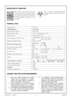
2-position directional spool valve without return springs. The spool is positioned and supported with attached solenoid. There is no neutral position as the spool is not WE6...-12/...B... - directional spool valve designation like that, has throttle insert in TECHNICAL DATA ASSEMBLY AND APPLICATION REQUIREMENTS 1. Only valve working properly and suitably installed may be connected to an electric system. Only skilled workers are allowed to connect and disconnect electric system. 2. Ground connection ( i ) must be connected with protective earth wire ( PE ) in supply system according to appropriate...
Open the catalog to page 2
Graphic symbols for 3- position directional spool valves Graphic symbols for spools Graphic symbols for 2- position directional spool valves Spool E has the version E1 with indirect positions like for spool P Flow section in central position for spools: Q, W - according to page 2
Open the catalog to page 3
Graphic symbols for 2- position directional spool valves Graphic symbols for spools working and indirect working
Open the catalog to page 4
OVERALL AND CONNECTION DIMENSIONS 5 O O 9,4 - 4 depth holes 5,3 - 4 holes 4 15 3 B H A a 23 42 47 56,5 b 1 8 45 2 6 154 31 32,5 45 T A B 0,75 P 40,5 73 8,7 17 154 9 7 218 type electrical connecti on typ e plug-in-connectors control voltage - DC ISO 4400 type 12V , 24V , 110V plug-in-connectors control voltage - AC ISO 4400 type 110V , 230V with rectifie r dimension dimensi on H 86 93 O M5 depth10 - 4 holes 7,6 (max) - 4 holes (P,T,A,B) 10 T B 26,55 31,75 32,5 A 10,3 19 27,8 40,5 min 73 r 5,95 16,25 P 0,75 min 45 1 - Solenoid a 2 - Solenoid b 3 - Plug-in-connector A (ISO 4400 type) 4 - Plug-in-connector...
Open the catalog to page 5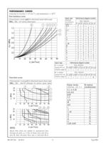
PERFORMANCE CURVES measured at viscosity = 41mm2/s and temperature t = 50°C Flow resistance curves Characteristic curves p(Q) for directional spool valves type WE6...-12/... for various spool types_ Flow limits curves Characteristic curves p-Q for directional spool valves type WE6...-12/... with DC solenoids for various spool types Above flow limits are related to symmetrical flow through all ports i.e. if the oil flows from port P to port A, then the same flow rate is from port B to
Open the catalog to page 6
Spool position monitoring Additional technical data Scheme of electrical connection of inductive switch Contact allocation (pins Graphic symbols for directional control valves and initial positions of switches Initial position of inductive switch depending on the spool position 0 - off neutral state on output coctact (NO - contact A; NC - contact 2) 1 - on state on uotput contact (NO - contact A; NC - contact 2) directional control 3-position directional control valve Normally open spool position [%] Normally closed Normally open spool position [%] Normally closed
Open the catalog to page 7
Spool position monitoring Initial position oF inductive switch depending on the spool position directional control 2-position directional control valve WE6...A (positions: a, 0) solenoid and switch on side "a" spool position [%] spool position [%] 2-position directional control valve WE6...B (positions: 0, b) solenoid and switch on side "b" spool position [%] spool position [%] 2-position directional control valve WE6A, D, C; .../0; .../OF spool position [%] spool position [%] 2-position directional control valve WE6B, Y spool position [%] spool position [%]
Open the catalog to page 8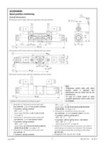
ACCESSORIES Spool position monitoring erall dimens mensi Overal l di mens ions Directional control valve with two solenoids and two switches M 12 x 1 B 103 A min 70 5 23 57,5 b a 72,5 30 6 73 1 45 278 Directional control valve with one solenoid and one switch 2 184 B O 31 45 T A 0,75 P 40,5 17 8,7 3 184 Directional control valve with two solenoids and one switch A B a 42 b 4 248 Subplate surface required according to page 5 1 - Dimension of directional control valve with soleno lenoids positio ositi two so leno ids - a, b and two p ositi on switches • 3-po sit io n, springs centered 3-position...
Open the catalog to page 9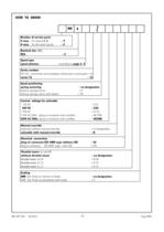
Number of service ports Spool type spool schemes Series number (10-19) - connection and installation dimensions unchanged = 1X Spool positioning spring centering without springs return without springs return with detent Control voltage for solenoids 110V AC 50Hz (plug-in-connector with rectifier) 230V AC 50Hz (plug-in-connector with rectifier) Manual override solenoids without manual override solenoids with manual override Electrical connection plug-in-connector ISO 4400 type without LED plug-in-connector ISO 4400 type with LED Throttle insert (in port P) without throttle insert NBR (for fluids...
Open the catalog to page 10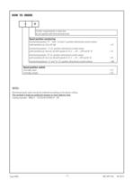
Further requirements in clear text (to be agreed with the manufacturer) Spool position monitoring monitored position "0"- "zero" (3 and 2- position directional control valves monitored position "a" (2- position directional control valves with positions (a, 0) or (a, b) with spools A, D, C, .. JO;.. ./OF and' B, Y) = A monitored position "b" (2- position directional control valves with positions (0, b) or (a, b) with spools A, D, C, .../O .../OF and B Y) = B monitored positions "a" and "b" (3- position directional control valves)_= AB Spool position switch Directional spool valve should be ordered...
Open the catalog to page 11All PONAR S.A. catalogs and technical brochures
 PRESSURE SWITCH TYPE USPH 1
4 Pages
 MK series
4 Pages
 MG series
4 Pages
 ZRR6
ZRR68 Pages
 UZKB 6
6 Pages
 DZ5DP
DZ5DP6 Pages
 DR5DP
DR5DP6 Pages
 UZPD30
8 Pages
 Reverse valve type URJP10
4 Pages
 General Catalogue
1200 Pages
 Catalogue products
20 Pages


Archived catalogs
 Blocks
4 Pages
 Hydraulic Systems
41 Pages
 Hydraulic Cylinders
11 Pages
