- Catalogs
- Pneumat Systems
- BinDrill
BinDrill
1 /40Pages
BinDrill
1 /40Pages
Catalog excerpts
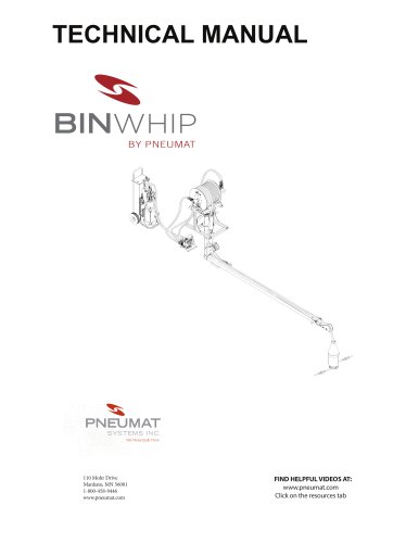
TECHNICAL MANUAL DIMEN TOLERA FRACTI ANGUL TWO PL THREE P 110 Mohr Drive Mankato, MN 56001 1-800-458-9446 www.pneumat.com
Open the catalog to page 1
BinDrill Technical Manual We Make Bulk Flow We here at Pneumat Systems would like to thank-you for your purchase of a Bin Drill. We are constantly striving to keep Bin Whip & Bin Drill the best bulk storage cleaning equipment available. One of the key ways we can do just that is to listen to you. This is important for two reasons. First, included in your purchase is the commitment from us to stand behind our product and keep you up and running. If you need something we will get it to you most times the next day. Second, many of the improvements we have incorporated over the years, have come from...
Open the catalog to page 2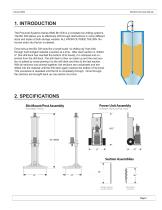
BinDrill Technical Manual 1. INTRODUCTION The Pneumat Systems Series 8000 Bin Drill is a complete bin drilling systems. The Bin Drill allows you to effectively drill through obstructions in many different sizes and styles of bulk storage vessels. ALL FROM OUTSIDE THE BIN. No human entry into the bin is needed. Once set-up the Bin Drill acts like a small-scale “oil drilling rig” that drills through hard bridged material a section at a time. After each section is “drilled in” (the drill deck has reached the bottom of its travel), it is clamped and unpinned from the drill deck. The drill deck is...
Open the catalog to page 3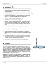
BinDrill Technical Manual First and foremost , you should understand and follow all safety procedures for your facility. This is the safety-alert symbol. When you see this symbol be alert to the potential of personal injury. Read this manual to learn how to safely operate this equipment and its controls. Do not let anyone operate without proper instruction. Only ONE operator should use the BinDrill at a time. Do NOT use gloves while operating the BinDrill. Keep your Bin Drill in proper working condition. Unauthorized modifications to the machine may impair the function and/or safety of the machine....
Open the catalog to page 4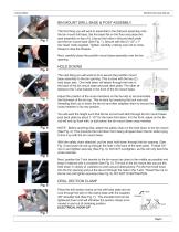
BinDrill Technical Manual BIN MOUNT DRILL BASE & POST ASSEMBLY The first thing you will want to assemble is the drill post assembly onto the bin mount drill base. Set the base flat on the floor and place the post assembly on top of it. Line-up the holes in the post deck plate and the bin mount base (See Fig. 1). Secure with the (2) 1/2" x 1" hex head bolts supplied. Tighten carefully, making sure not to crossthread or strip the threads. Next, carefully place the post/bin mount base assembly over the bin opening. HOLD DOWNS The next thing you will want to do is secure the post/bin mount base assembly...
Open the catalog to page 5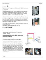
BinDrill Technical Manual CAUTION! All electrical connections should be made by your facility electrician or other authorized personnel only. See the motor faceplate (Fig. 9A) for specific electrical requirements The wiring diagrams for both high and low voltage configurations are located on the inside of the electrical box cover on the motor (See Fig. 9A). NOTE: Make sure you wire the motor in the proper configuration for the voltage you are hooking-up (damage to the motor can occur if wired wrong). Fig. 9A There is a proper direction the motor must spin in order to pump correctly. To determine...
Open the catalog to page 6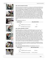
BinDrill Technical Manual DRILL DECK UP/DOWN CONTROL Moving of the drill deck up and down is controlled by the SPRING-CENTERED directional valve (See Fig. 12). NOTE: A spring centered valve is one that when moved from the center position and released it will “spring” back to the center position. Hook-up the DRILL DECK UP/DOWN Control circuit (this block is labeled “DRILL DECK UP/DOWN”). This circuit controls the up/down movement of the ball screw and drill deck assembly. Take the 10 ft hydraulic hose with the “red” color coding at the ends and attach the “red” Male Quick Disconnect (QD) to the...
Open the catalog to page 7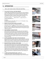
BinDrill Technical Manual DRILL SECTIONS DOWN THROUGH MATERIAL CALCULATE # OF DRILL SECTIONS NEEDED To begin drilling, first estimate how many sections you will be needing to reach your desired depth. (NOTE: Knowing exactly how deep to drill will keep you from drilling into the bin bottom or other known obstruction.) To calculate the number of sections, take the depth you want to drill to, subtract the bit length, and divide that by length of a drill section. # of Sections Needed = Depth of Bin (FT) - Length of Bit (FT) ÷ Length of Drill Section (FT) EXAMPLE To drill 60 feet with a Series 8000:...
Open the catalog to page 8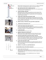
BinDrill Technical Manual MOTOR. After checking the clamp, pull the cross pin out With the UP/DOWN control valve, run the drill deck up to within a few inches of the top. 7. BOLT NEW SECTION ONTO CLAMPED SECTION Place the pin of the new section into the receiver end of the clamped section and secure with 3/8" cross bolt and nut. 8. ALIGN & PIN DRILL SECTION Bring drill deck down SLOWLY and guide the pin into the receiver of the drill section (see Fig. 27). Align line the cross holes and insert the pin. Flip the handle on the Drill Disconnect to rotate the pin on the U-Joint freely as needed to...
Open the catalog to page 9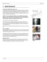
BinDrill Technical Manual 7. MAINTENANCE HYDRAULIC POWER UNIT (See Fig. 31) The fluid level in the reservoir should be checked daily and filled if necessary. To check the level look at the sight guage on the front of the reservior. The oil should be visible at the bottom of the guage when the oil is cold (when oil is warm the level should be approx in the middle of the guage (see Fig. 32). If it is low you must fill to the correct level. NOTE: The oil supplied with the unit is ISO 46 food grade hydraulic oil and can be purchased from Pneumat Systems. Total system capacity is approximately 11gal....
Open the catalog to page 10
BinDrill Technical Manual
Open the catalog to page 11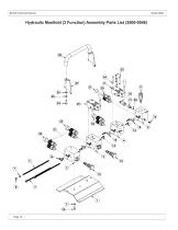
BinDrill Technical Manual Hydraulic Manifold (3 Function) Assembly Parts List (2500-0046)
Open the catalog to page 12
BinDrill Technical Manual
Open the catalog to page 13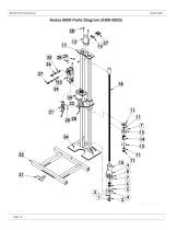
BinDrill Technical Manual 4 Series 8000 Parts Diagram (5300-0003) 4 UNLESS OTHERWISE SPECIFIED: DIMENSIONS ARE IN INCHES TOLERANCES: FRACTIONAL .063 ANGULAR: MACH 1° BEND 2° TWO PLACE DECIMAL .030 THREE PLACE DECIMAL .010 Customer
Open the catalog to page 14All Pneumat Systems catalogs and technical brochures
 Safety Data Sheet
9 Pages
 BinWhip
53 Pages
 Cardox
32 Pages
 AIRBLASTTRUCKUNLOADER
2 Pages
 blast.
4 Pages
 drill.
2 Pages
 RAPIDLYUNLOAD HUNG-UPPRODUCT
2 Pages