P4 • P5/EP5
1 /42Pages

P4 • P5/EP5
1 /42Pages
Catalog excerpts

alve Control System
Open the catalog to page 1
Manufacturers declaration • Hersteller-Erklärung • Déclaration de fabricant GB Manufacturers declaration in compliance with EC directive 89/ 392/ EEC, annex I I B and 89/ 336/ EEC. We hereby confirm that the appliances described in this sheet has been manufactured in compliance with the applicable standards and is intended for installation in a machine/ application, and that commissioning is strictly prohibited until evidence has been provided that the machine/ application in question is also in compliance with EC directive 89/ 392/ EEC and 89/ 336/ EEC. This manufacturers declaration is applicable...
Open the catalog to page 3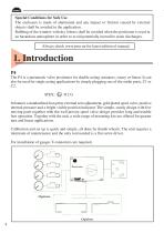
Special Conditions for Safe Use The enclosure is made of aluminium and any impact or friction caused by external objects shall be avoided in the application. Rubbing of the window with dry fabrics shall be avoided when the positioner is used in an hazardous atmosphere in order to avoid potentially incendive static discharges. Always check www.pmv.nu for latest edition of manual. 1. Introduction P4 The P4 is a pneumatic valve positioner for double acting actuators, rotary or linear. It can also be used for single acting applications by simply plugging one of the outlet ports, C1 or C2. ATEX: It...
Open the catalog to page 4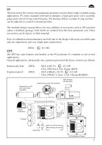
P5 The base unit of the system is the pneumatic positioner, used in either single or double acting applications. P5 comes standard with built in dampers, a high gain spool valve assembly, gauge ports and an O-ring sealed housing. The housing utilizes a unique O-ring seal that can be adjusted to a sealed or drained position. The modular design concept allows for easy addition of accessories such as I/P converter and/or a feedback package, both which are isolated from the basic pneumatic unit. These accessories can be factory or field mounted. Ease of calibration and maintenance are built into...
Open the catalog to page 5
2. Storage instructions PMV Positioner and feedback module storage and handling procedures PMV Positioners and feedback modules are precision instruments which should be stored and handled accordingly to avoid problems or damage. Electropneumatic positioners/feedback modules contain electronic components which can be damaged by exposure to water. Appropriate precautions should be taken to protect units while in storage. Warehouse storage Stored in original PMV shipping containers, units should be stored in an environmentally controlled area, i.e. clean, cool (15-26°C, 60-80°F) and dry, out of...
Open the catalog to page 6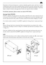
Dependent on the local temperature variations, humidity and dew points and time in storage condensation could occur and accumulate inside on the I/P Converter causing erratic operation or failure due to water and corrosion. The potential for condensation damage is especially high in southern climates and aggravated if units are exposed to direct sunlight. For further assistance, please contact you nearest PMV office. Storage Seal (P5/EP5) P5/EP5 is supplied with all enclosure entry points sealed.The seal is only a storage seal, not to be used as seal when P5/EP5 is in operation. If Storage Seal...
Open the catalog to page 7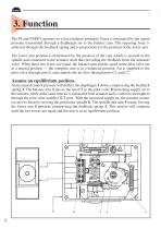
3. Function The P4 and P5/EP5 operates on a force balance principal. Force is originated by the signal pressure transmitted through a diaphragm on to the balance arm. The opposing force is achieved through the feedback spring and is proportional to the position of the lower arm. The lower arm position is determined by the position of the cam which is secured to the spindle and connected to the actuator shaft thus providing the feedback from the actuator/ valve. When these two forces are equal, the balance arm and the spool in the pilot valve are in a neutral position — the complete unit is in...
Open the catalog to page 8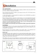
4. Installation Air requirements Maximum supply pressure is 1 MPa (150 psi). Supply air shall be clean, dry and free from oil, water, moisture, foreign parts and debris. The air shall be freeze-dried or similar to a dew point of at least 10°C (18°F) below lowest expected ambient temperature. A <40µ filter/regulator is recommended to be installed as close to P4/P5/EP5 as possible to ensure proper supply air quality. Before making pneumatic connections to the positioner, it is recommended that the supply air lines are opened up and allowed to vent for 2-3 minutes to clear any debris from the line....
Open the catalog to page 9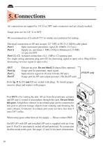
5. Connections Air connections are tapped for 1/4" G or NPT male connectors and are clearly marked. Gauge ports are for 1/8" G or NPT. We recommend use of Loctite® 577 or similar user preferred for sealing. Electrical connection on I/P unit accepts 1/2" NPT or PG 13,5 (M20) cable gland. Port I Input instrument pneumatic signal 20-100kPa (3-15 psi) Port S Supply air, maximum 1 MPa (150 psi) Minimum 0,15 MPa (21 psi) for EP5 Port C1, C2 Actuator connections (0,2-1 MPa). C2 opening port. For single acting operation plug port C1 for increasing signal to open valve. Plug C2 for decreasing (reverse)...
Open the catalog to page 10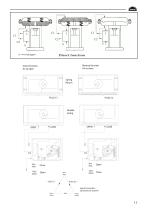
Direct function Reverse function Air to open Air to close
Open the catalog to page 11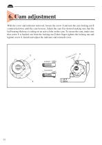
6. Cam adjustment With the cover and indicator removed, loosen the screw 1 and turn the cam locking nut 2 counterclockwise until the cam loosens. Adjust the cam 3 as desired making sure that the ball bearing 4 always is riding on an active lobe on the cam. To secure the cam, make sure that screw 1 is backed out from the locking nut 2 then finger tighten the locking nut and tighten screw 1. Install and adjust the indicator and reinstall cover.
Open the catalog to page 12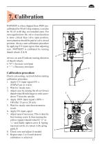
P4/P5/EP5 is when shipped from PMV precalibrated for 90 ±0,5 deg rotation, (can also be 30, 45 or 60 deg, see installed cam). For most applications the valve closed position is more critical than valve open position, most attention should be paid at valve closed position. Always start calibration procedure by applying 0 % input signal, then adjusting zero. P4/P5/EP5 is calibrated by turning thumb wheels 1 & 4. Arrows on arm 5 indicate turning direction of thumb wheels. < “+“ = Increase zero/span > “-“ = Decrease zero/span Calibration procedure Check cam seating, section 6 before starting calibration...
Open the catalog to page 13All PMV catalogs and technical brochures
 F5 Feedback unit
6 Pages
 ValveSight
8 Pages
 PMV D3 Digital Positioner
56 Pages


- Illuminated indicator
- LED indicator
- Position indicator
- 4-20 mA indicator
- Rotary positioner
- Linear positioner
- Rotary valve positioner
- Compact positioner
- Pneumatic valve positioner
- Linear valve positioner
- Transmitter indicator
- Digital positioner
- Electro-pneumatic valve positioner
- Electro-pneumatic positioner
- Explosion-proof panel meter
- Digital valve positioner
- Modular indicator