PML711A-RO
1 /5Pages

PML711A-RO
1 /5Pages
Catalog excerpts
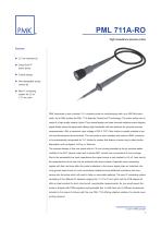
PML 711A-RO High impedance passive probe Features: 2.5 mm diameter tip CeramCoreTM hybrid probe Coaxial design Interchangeable spring contact tip New IC contacting system for 0.5 to 1.27 mm pitch PMK introduces a new universal 10:1 miniature probe for oscilloscopes with up to 500 MHz bandwidth. As all PMK probes the PML 711A features CeramCoreTM technology. The entire probe core is made of a high quality ceramic hybrid. Pure coaxial design and laser trimmed resistors ensure highest signal fidelity along the signal path offering high bandwidth and fast risetimes for accurate impulse measurements. With a maximum input voltage of 300 V CAT II this divider is equally suitable in service and development environments. The new probe is also available with read-out BNC connector to be automatically recognised as 10:1 divider by scopes that feature a sense ring to detect probe attenuation such as Agilent, LeCroy or Tektronix. The compact design of this new probe with its 2.5 mm housing diameter at the tip provides better visibility to the DUT (device under test) in dense SMT circuits than conventional 5 mm housings. Due to the remarkably low input capacitance the signal source is only loaded by 9.5 pF. Less load to the measurement circuit can only be achieved with active probes. Especially when measuring signals with fast rise times often the probe‘s adaption to the source signal plays an important role. Long ground leads found on most conventional adaptions bring additional inductance and resonances into the setup which will result in false or inaccurate readings. The new IC contacting system consisting of five different IC adapters ranging from 1.27 to 0.5 mm pitch and the PCB adapter kit offer an ideal solution for short circuit-proof, reproducible measurements. As you would expect the probe is shipped with PMKs signature spring-loaded tips. In total there are 16 different accessories included in the scope of delivery with the new PML 711A offering adaptive solutions for almost every probing demand.
Open the catalog to page 1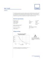
This datasheet supersedes all previously published material. Specifications that are defined typical are not guaranteed and are published as general information to the user. The instrument should have warmed up for at least 20 minutes and the environmental conditions must not exceed the specified limits of the probe. Note that specifications are subject to change without notice. Electrical specifications Attenuation ratio (1) 10:1 ± 2 % at DC Voltage coefficient 0.00025 % / V (typical) System bandwidth 500 MHz (-3 dB) System risetime 700 ps (10% – 90 %) (typical) Maximum rated input voltage (2)...
Open the catalog to page 2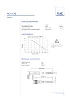
Input resistance (system) Input capacitance (system) Compensation range Input coupling of the measuring instrument Input impedance Typical Input Impedance PML711 100M 10M Note that the input impedance of the probe decreases as the frequency of the applied signal increases. Mechanical characteristics Weight (probe only) Cable length Probe tip diameter
Open the catalog to page 3
Environmental specifications Altitude Temperature range Maximum relative humidity operating non-operating operating non-operating operating up to 2000 m up to 15000 m 0 °C to +50 °C -40 °C to +71 °C 80% relative humidity for temperatures up to +31 °C, decreasing linearly to 40 % at +50 °C Declaration of conformity The manufacturer declares the conformity of his products with the actual required safety standards in accordance with the Low Voltage Directive (LVD) 2006/95/EC: CEI/IEC 61010-031:2008 Safety requirements for electrical equipment for measurement, control and laboratory use. Part 031: Safety...
Open the catalog to page 4
Scope of delivery PML 711A-RO order No. 855-711-A01 ■ 2 footer positioner ■ 2 self adhesive Cu pads ■ Adjustment tool T ■ Coding rings (set) 3 x 4 colors ■ Ground blade 2.5 ■ Ground lead 15 cm ■ Ground spring 2.5 ■ IC-Caps 0.5 to 1.27 mm pitch ■ Instruction manual ■ Insulating cap 2.5 ■ PCB adapter kit 2.5 ■ Probe ■ Protection cap 2.5 ■ Solid tip CuBe 0.5 mm ■ Spring tip 0.5 mm ■ Sprung hook 2.5 Safety information To avoid personal injury and to prevent fire or damage to this product or products connected to it, review and comply with the safety informations stated in the manual before using...
Open the catalog to page 5All PMK catalogs and technical brochures
 PMTG321A
5 Pages
 PMTG311A-RO
5 Pages
 PMT221A
5 Pages
 PMT211A-RO
5 Pages
 PMT201A-RO
4 Pages
 PMM511A-RO
5 Pages
 PMM311A-RO
5 Pages
 PMM301A-RO
4 Pages
 PMS221A
5 Pages
 PMS211A-RO
5 Pages
 PMS201A-RO
4 Pages
 PHT312-RO
4 Pages
 PML791-RO
5 Pages
 PML751-RO
5 Pages
 PML721-RO
1 Page
 PML701-RO
3 Pages
 PML311-RO
5 Pages
 PML211-RO
5 Pages
 Tetris1000
6 Pages
 Sonic
Sonic3 Pages
 BumbleBee®
6 Pages
 TETRIS® 1000
6 Pages