- Catalogs
- PLUM Sp z.o.o
- MacR6 Z0
MacR6 Z0
1 /71Pages

MacR6 Z0
1 /71Pages
Catalog excerpts

USER MANUAL PROGRAM VERSION: MacR6-Z0JH2.10_S00104_V1307
Open the catalog to page 1
MAIN MENU
Open the catalog to page 2
SAFETY SAFETY CONDITIONS With the help of signs presented below there are important informations distinguished in order to make the main functionalities and safety rules more clarified. Important information about safety rules or significant device feature Important information about device usage Utilize the package at the end of usage period in proper recycling company. Do not dump the product with normal garbage. Do not burn the product.
Open the catalog to page 3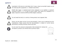
SAFETY Exploitation of the device is permitted only in areas, where turned GSM modem on will not interrupt other equipment, i.e. medical instruments. MacR6 data logger is explosive-proof device designed to be installed in explosive hazardous zones 0, 1, 2. In order to ensure safety rules, before the installation it is highly required to read the INSTALLATION chapter cautiously. Do not install the device in vincinity of strong electric and magnetic field. Always use the latest revision of this documentation, which can be obtained from the manufacturer. Please ensure that this documentation is...
Open the catalog to page 4
TECHNICAL DATA CONTENTS – TECHNICAL DATA MAIN MENU
Open the catalog to page 5
TECHNICAL DATA BASIC INFORMATION MacR6-Z0 is the telemetric pulse from gas meter recorder. Programmed parameters, as pulse factor and combustion heat allow for calculation and registering gas energy and volume consumption. MacR6-Z0 data logger has ability to count pulses from gas meter using internal terminal board - cable connection, or directly by magnetic coupling with gas meter totalizer. Universality of this solution makes MacR6-Z0 compatible with diaphragm, rotary and turbine gas meters. Depending on the hardware variant there is also possibility of gas pressure and temperature measurement....
Open the catalog to page 6
TECHNICAL DATA ■Pressure sensor:|l||H||| USER MANUAL
Open the catalog to page 9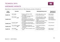
TECHNICAL DATAHARDWARE VARIANTS Depending on requirements PLUM Ltd. offers following variants of MacR6-Z0:
Open the catalog to page 10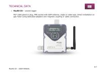
TECHNICAL DATA • MacR6-Z0 – volume logger PG7 cable gland or plug, FME socket with GSM antenna; angle or cable type. Direct installation on gas meter using dedicated adapters and magnetic coupling or cable connection.
Open the catalog to page 11
TECHNICAL DATA • MacR6-Z0-P/LPT – pulse, temperature and pressure logger PG7 cable gland or plug, FME socket with GSM antenna, external pressure sensor, Pt1000 temperature sensor, connection to the gas meter cable
Open the catalog to page 12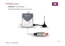
TECHNICAL DATA • MacR6-Z0-P – pressure logger FME socket with GSM antenna, pressure sensor
Open the catalog to page 13
TECHNICAL DATA • MacR6-Z0-P/2P – two pressure logger: PG7 cable gland or plug, FME socket with GSM antenna, two pressure sensors
Open the catalog to page 14
TECHNICAL DATA • MacR6-Z0/2V – volume logger: Two PG7 glands, FME socket with GSM antenna. Designed for work with two separated gas meters – two standalone counters. Only cable connection.
Open the catalog to page 15
INSTALLATION CONTENTS - INSTALLATION MAIN MENU
Open the catalog to page 16
INSTALLATION RF-1 – TYPE GAS METER
Open the catalog to page 17
INSTALLATION SIM CARD ASSEMBLY To insert the SIM card take off the front cover. Remove six TORX T10 screws from back of the cover. Next place the Micro SIM card into the holder as shown in the picture. There is no need to remove the battery to insert the SIM card. SIM card must meet the requirements of ETSI TS 102221 v 9.0.0 or Embedded-SIM it is essential for proper device operation in whole temperatures range. In the next step put the device together and tighten the screws with 0,65-0,75Nm momentum. SIM card assembly is allowed only out of the hazardous explosive zone.
Open the catalog to page 18
INSTALLATION Delivered devices may have the display turned off. That is the storage mode in order to save the battery energy. Turning on the device is able by placing the magnet (i.e. OptoBTEx head) to the OPTICAL INTERFACE window. This will cause showing the "SLEEP 3" information on the display. All of indicators on the left side of the display will flash, and then they will be shutting down in a row. Repeated magnet closing before the indicators disappearing will result the "SLEEP 2" information on the display, next "SLEEP 1" and "START" - after the indicators shutdown the device will turn...
Open the catalog to page 19
INSTALLATION DEVICE ASSEMBLY MacR6-Z0 data logger is the device designed for installation in hazardous explosive zones 0, 1, 2. Connecting external antenna cable is allowed only out of the explosive zone. Antenna socket should be covered by special sleeve attached to the antenna cable. Minimum requirements for improving the safety and health protection of workers potentially at risk from explosive atmospheres are prescribed in Directive 1999/92/EC of the European Parliament and of the Council of 16 December 1999 (ATEX 137 'Worker Protection Directive'). Installation enviroment must guarantee...
Open the catalog to page 20
INSTALLATION BK-TYPE AND UG-TYPE GAS METER ASSEMBLY MacR6-Z0 allows for direct connection using magnetic coupling with BK-type and UG-type gas meter totalizers MacR6-Z0 assembly process: • Place the proper adapter to the gas meter totalizer Adapters to the UG, GL-type, BK-type and RF-1 gas meters • attach the data logger to the adapter by sliding it in with the exserted part on the top to the gas meter totalizer, and to tighten two side sealing screws.
Open the catalog to page 21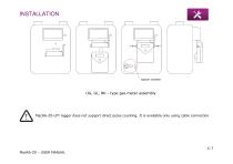
spacer washer UG, GL, BK - type gas meter assembly MacR6-Z0-LPT logger does not support direct pulse counting. It is available only using cable connection.
Open the catalog to page 22
INSTALLATION RF-1 – TYPE GAS METER ASSEMBLY MacR6-Z0 on RF-1 gas meter type: • replace the default front cover for the additional with emitter and cable inserted through – delivered with the adapter • connect the wires to the terminals board in MacR6-Z0 device: Signal Pulse input Wire Yellow Terminals board in MacR6-Z0 recorder
Open the catalog to page 23
INSTALLATION • arrange the cable inside the device cover between the edge and blocking bolts to avoid the cable squeezing, or other damage caused by exserted elements of electronic parts • preliminarily tighten the cover with screws only in holes, which will not be used to attach the adapter
Open the catalog to page 24All PLUM Sp z.o.o catalogs and technical brochures
 MacREJ 5
4 Pages
 MacMAT IV Flow Computer
4 Pages
 MacR6N
4 Pages
 MacR6
MacR64 Pages
 MacBAT5
4 Pages
- Data logger
- Pressure gauge
- Data-logger with screen
- Wireless datalogger
- Datalogger without display
- Gas pressure gauge
- Monitoring datalogger
- Datalogger with LCD display
- Digital pressure gauge
- Compact datalogger
- Diaphragm pressure gauge
- High-accuracy pressure gauge
- Flow datalogger
- Flow computer
- Intrinsically safe pressure gauge
- Data logging pressure gauge
- Intelligent data logger
- Gas flow computer
- Volume corrector
- Gas volume corrector