
- Catalogs
- PiezoMotor AB
- PMD101 Technical Manual


PMD101 Technical Manual

PMD101 Technical Manual
The technical manual provides guidance on installing and using the PiezoMotor Microstep Driver 101 (PMD101), designed for controlling Piezo LEGS linear and rotary motors. It enhances motor resolution to the nanometer/microradian range by dividing each full waveform step into precise microsteps.
- Symbols: Symbols indicate caution, regulations, and notes for safe and effective use.
- Safety Instructions: Emphasizes proper handling of the PMD101 to ensure performance and reliability, including discharging motors, proper installation, ventilation, ESD protection, and correct motor lead connections.
The PMD101 package includes the driver unit, USB cable, AC-DC adaptor, and a CD with software and documentation.
- Piezo LEGS Motors: High precision and resolution motors operating through friction-based direct drive without gearboxes.
- Motor Drive Principle: Requires four electrical signals to activate motor legs, with speed controlled by signal frequency.
- Microstepping Driver: Provides high-resolution control with up to 2048 microsteps per waveform step.
- Waveforms and Voltages: Delivers 42 VPP signals with various waveforms optimized for performance.
Guides on initial setup, including cooling, power supply, communication, and motor/encoder connections.
In-depth technical specifications and operational details of the PMD101.
Details on command usage for controlling the driver, including status and settings commands.
Instructions for installing the PMD101, including dimensions and connector pinouts.
Describes driving modes (closed and open loop) and software for motion control.
Parameters for closed loop target mode and other settings like parking, limits, and encoder configurations.
General maintenance tips, troubleshooting, and firmware update procedures.
Conditions and terms of the warranty for the PMD101.
The document outlines the resolution settings for the PMD101 driver unit, supporting different waveform resolutions. Higher resolutions limit the maximum waveform frequency.
The PMD101 driver allows users to set waveform frequency and automatically selects the appropriate microstep resolution. Users must consider power consumption and maximum speed limitations.
Provides step-by-step instructions for setting up the PMD101 unit, including unpacking, software installation, motor connection, and initial configuration.
The driver unit requires adequate cooling and is powered by a 12-24 V DC supply. Proper motor and encoder connections are crucial.
The PMD101 driver uses a command structure in plain ASCII format, with commands for setting and reading various parameters.
The driver unit communicates with a host PC using a virtual RS232 port. Communication settings include a baud rate of 57600.
Users are cautioned to ensure correct motor phase connections to prevent damage.
Includes the ability to write settings to non-volatile memory and monitor motor performance.
The status command 'u' provides a response indicating various status flags.
These commands configure various parameters of the PMD101 driver unit.
The PMD101 driver unit should be installed in a clean, dry environment with proper ventilation.
The PMD101 supports both open and closed loop operation for driving Piezo LEGS motors.
The analog interface is activated by connecting pin 9 to GND, with motion control signals connected to specific pins.
The software facilitates the use of Piezo LEGS motors and is available on the installation CD or the PiezoMotor website.
To operate in closed loop target mode, an encoder is required for position feedback.
Includes parking and initialization, external limits, encoder direction and type, and more.
The PMD101 requires no regular maintenance. Troubleshooting involves checking error codes and wirings.
Warranty conditions follow Orgalime S2012 standards.
Catalog excerpts
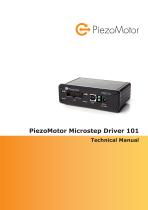
PiezoMotor Microstep Driver 101 Technical Manual
Open the catalog to page 1
Imprint Revision 02 11.04.2014 Document number 150086-02 © Copyright by PiezoMotor Uppsala AB Stålgatan 14, SE-754 50 Uppsala, Sweden All rights reserved, icluding those to the translation. No part of this description may be duplicated, reproduced, stored in an information system or processed or transferred in any other form without prior express written permission of PiezoMotor Uppsala AB.
Open the catalog to page 2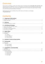
This document is intended as a guide to the technical aspects of installing and using PiezoMotor Microstep Driver 101 (hereafter referred to as PMD101). The unit is an advanced one axis driver for Piezo LEGS linear and rotary motors from PiezoMotor. The driver will give the motors resolution down in the nanometer/microradian range by dividing every full wfm-step into small and precise microsteps. Detailed information about the different Piezo LEGS motors can be found on our homepage: 3.1 Piezo LEGS Linear and Rotary Motors 5 - Detailed Technical Description 7.3.1 Motor Port Pinouts 7.3.2 Sensor...
Open the catalog to page 3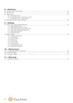
8.3.1 Internal Step Control 8.3.2 External Step Control - Step/Direction Interface 8.3.3 External Step Control - Analog Interface 9.1.2 Target Mode Position Limits A and B 9.1.3 Target Mode Minimum and Maximum Speed 9.1.4 Target Mode Speed Ramp Up and Down 9.1.5 Target Mode Stop Range 9.1.6 Target Mode Model 9.2.8 Analog Mode Stop Voltage 9.2.9 Analog Mode Stop Range 10.1 General Maintenance Instructions
Open the catalog to page 4
1 ‒ Important Information 1.1 Symbols Used in this Document Caution! This pictogram with the wording “Caution!” indicates an imminent danger which can result in slight physical injuries or material damage. ►This arrow points out the appropriate precautions. Regulation! This pictogram with the wording “Regulation!” indicates a statutory regulation, guideline or directive which must be observed in respective context of the text. Note! This pictogram with the wording “Note” provides tips and recommendations for use and handling of the component. Chapter 1 ‒ Important Information
Open the catalog to page 5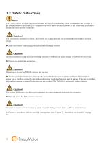
1.2 Safety Instructions Note! The PMD101 driver is a high-end product intended for use with PiezoMotor’s Piezo LEGS product line. In order to get best performance and reliability it is important the driver unit is handled according to the instructions given in this manual and other delivery documents. Caution! The piezoceramic elements in a Piezo LEGS motor act as capacitors and can sometimes hold substantial electrical charge. ► Make sure motors are discharged through suitable discharge resistors. Caution! Incorrect installation using improper mounting materials or methods can cause damage to...
Open the catalog to page 6
2 ‒ Delivery 2.1 Packaging and Delivery Contents The PMD101 driver unit has been cleaned prior to packaging, but does not carry any clean room classifications. The unit is shipped in a cardboard box with foam packaging material. These items are included in the box at delivery: 1x 1x 1x 1x PMD101 driver unit USB cable AC-DC adaptor, 15V, 1.2 A CD with PiezoMotor Motion System software and pdf-version of this document (latest verion of software and manual is available on the PiezoMotor homepage)
Open the catalog to page 7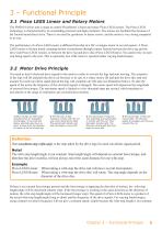
3 ‒ Functional Principle 3.1 Piezo LEGS Linear and Rotary Motors The PMD101 driver unit is made to control PiezoMotor’s linear and rotary Piezo LEGS motors. The Piezo LEGS technology is characterized by its outstanding precision and high resolution. The motors are backlash free because of the friction based direct drive. There is no need for gearboxes or linear screws, and the motor is very strong compared to its size. The performance of a Piezo LEGS motor is different from that of a DC or stepper motor in several aspects. A Piezo LEGS motor is friction based, meaning motion is transferred through...
Open the catalog to page 9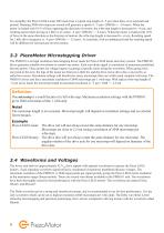
To exemplify, the Piezo LEGS Linear 20N motor has a typical step length of ~5 µm when there is no external load present. Running 2000 wfm-steps per second will generate a speed of ~5 µm • 2000 Hz = ~10 mm/s. When the motor is loaded with 10 N of force opposing the direction of motion, the wfm-step length is decreased to ~4 µm, and resulting speed when driving at 2 kHz is of course ~4 µm • 2000 Hz = ~8 mm/s. When the motor is loaded with 10 N of force in the same direction as the direction of motion, the wfm-step length is increased to ~6 µm. Resulting speed for 2 kHz drive frequency is ~6 µm...
Open the catalog to page 10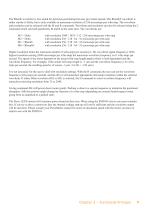
The Rhomb waveform is less suited for precision positioning but may give faster speeds. The RhombF waveform is rather similar to Delta, but is only available at maximum resolution of 256 microsteps per wfm-step. The waveform and resolution can be selected with the M and R commands. Waveform and resolution can also be selected using the C command which sets both parameters M and R at the same time. The waveforms are: M3 = Delta M2 = Delta M1 = Rhomb M0 = RhombF with resolution 2048 / 1024 / 512 / 256 microsteps per wfm-step with resolution 256 / 128 / 64 / 32 microsteps per wfm-step with resolution...
Open the catalog to page 11
4 ‒ Quick Start 4.1 Getting Started 1. Unpack the PMD101 unit and verify that no damage has occurred during transportation. Place unit so that it gets sufficient cooling. To install PiezoMotor Motion System software, run Windows Installer (msi file) from the CD, or find the latest release on our homepage: www.piezomotor.com. Additionally, communication drivers from FTDI needs to be downloaded and installed separately. Find the virtual com port drivers on the FTDI homepage: www.ftdichip.com. Connect your Piezo LEGS motor to the PMD101 unit. If you are using a Piezo LEGS Linear Twin motor, it needs...
Open the catalog to page 13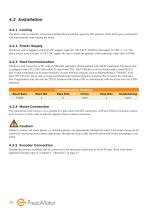
4.2 Installation 4.2.1 Cooling The driver unit is cooled by convection and therefore needs free space for this purpose. If the driver gets overheated it will automatically stop running the motor. 4.2.2 Power Supply The driver unit is supplied with a AC-DC adapter, input AC 100-240 V, 50/60 Hz and output 12 VDC, 1.5 A. The driver can be used with any 12-24 V DC supply (be sure to check the polarity of the connector; outer shell is GND). 4.2.3 Host Communication The driver unit connects to a PC with a USB cable and uses a serial interface with ASCII commands. The driver unit is equipped with a...
Open the catalog to page 14All PiezoMotor AB catalogs and technical brochures
 LR23-50
2 Pages
 LR23-80
2 Pages
 Analogue Driver PMCM31
4 Pages
 Microstepping Driver 206
2 Pages
 Piezo LEGS® Rotary Ø17mm
4 Pages
 PiezoMotor Brochure
8 Pages
 PMD101 - Microstep Driver
2 Pages
 Piezo LEGS Caliper 20N
4 Pages
 Piezo LEGS Rotary 50mNm
4 Pages
 Piezo LEGS Rotary 80Nmm
4 Pages
 Piezo LEGS Linear 6N
4 Pages
 Piezo LEGS Linear Twin-C 20N
4 Pages
 Piezo LEGS Linear Twin 20N
4 Pages
 Piezo LEGS WavePlate
4 Pages
 Piezo LEGS Linear Twin-C 40N
4 Pages
 Piezo LEGS® Rotary Ø17
4 Pages


- Electromotor
- DC electromotor
- Motor controller
- DC motor controller
- Motor with built-in encoder
- Stepper motor controller
- Multi-axis positioning controller
- Stainless steel motor
- DC motion controller
- Analog motor controller
- Single-axis motion controller
- Microstepping motor controller
- Positioning motion controller
- PID positioning controller
- Industrial motion controller
- Piezoelectric motor
- Piezoelectric motion controller
- Linear piezoelectric motor
- Non-magnetic piezoelectric motor