- Catalogs
- PiezoMotor AB
- Instalation Guidlines for Piezo LEGS Caliper
Instalation Guidlines for Piezo LEGS Caliper

Instalation Guidlines for Piezo LEGS Caliper
- Ensure the motor is always guided by surrounding mechanics. The drive rod must remain in contact with the drive legs to prevent damage.
- Mount the motor using 8 screws, ensuring alignment and preload of the drive legs.
- Follow the specified sequence for mounting screws to avoid misalignment.
- Mechanical end stops must be included in the design to prevent the stage from exceeding specified limits.
- For the goniometer version, the stroke varies with the radius, with a minimum radius of 86 mm.
- The linear version offers a stroke of ±14.5 mm from the center position.
- Remove the transport safety holder before installation.
- Feed cables through designated holes and ensure guiding pins align with guiding holes.
- Secure the motor base without forcing it, allowing for self-alignment.
- Use cable relief to secure cables.
Catalog excerpts
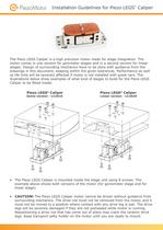
Installation Guidelines for Piezo LEGS® Caliper The Piezo LEGS Caliper is a high precision motor made for stage integration. The motor comes in one version for gonimeter stages and in a second version for linear stages. Design of surrounding mechanics have to be done with guidance from the drawings in this document, keeping within the given tolerances. Performance as well as life time will be severely affected if motor is not installed with great care. The illustrations below show examples of what kind of stages to build for the Piezo LEGS Caliper to be fitted inside. Piezo LEGS® Caliper Gonio version - LC2010 Piezo LEGS® Caliper Linear version - LC2020 • The Piezo LEGS Caliper is mounted inside the stage unit using 8 screws. The example above shows both versions of the motor (for goniometer stage and for linear stage). • CAUTION! The Piezo LEGS Caliper motor cannot be driven without guidance from surrounding mechanics. The drive rod must not be removed from the motor, and it must not be moved to a position where contact with any drive leg is lost. The drive legs will be severely damaged if they are not preloaded while motor is running. Repositioning a drive rod that has come out of place may crack the ceramic drive legs. Keep transport safty holder on the motor until you are ready to mount.
Open the catalog to page 1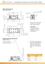
Installation Guidelines for Piezo LEGS® Caliper Main Dimensions 44 40 ±0,1 (2x) -0,002 3 g7 -0,012 0,03 A 3 8 60 ±0,1 60 20 1.6 (4x) M2 - 6H 44 5.2 4 20,4 3 • The stroke (using linear version) is ±14.5 mm from center position. • • CAUTION! Driving the motor outside of limits will damage the motor permanently. 14,4 3 20 8 20,4 ±0,1 0,01 10 ±0,02 5,2 ±0,02 15,7 20,7 A 20,7 5 ±0,03 15,7 ±0,03 Gonio and Linear 27 ±0,1 2.4 THRU ALL 4.4 2.4 (4 x) 54 Additional Specifications 103174 sample: Application (Stage radius 86mm max stroke ±10 deg) Name REV. Caliper Linear R 4,5 Radius tangency Gonio version...
Open the catalog to page 2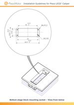
5,1 15,7 ±0,03 Installation Guidelines for Piezo LEGS® Caliper 0,02 C C SECTION A-A +0,2 50 0 +0,2 20,8 0 14,4 (8x) R1,5 (4x) M2 54 +0,2 60,5 0 REV. e Mock-up -.00 Bottom stage block mounting socket – View from below
Open the catalog to page 3
8 7 Installation Guidelines for Piezo LEGS® Caliper A 0,02 C 5,1 15,7 ±0,03 5 A C SECTION A-A +0,2 50 0 +0,2 20,8 0 14,4 (8x) R1,5 54 • It is very important that +0,2 mounting surfaces on 60,5 0 bottom and top blocks are parallel to within 0.02 mm. e Mock-up (4x) M2 REV. -.00 Cut plane through both stage blocks
Open the catalog to page 5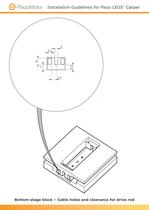
Installation Guidelines for Piezo LEGS® Caliper 7 6,5 8 4,5 4 5,9 Bottom stage block – Cable holes and clearance for drive rod
Open the catalog to page 6
Installation Guidelines for Piezo LEGS® Caliper Mounting instructions • Step one is to remove transport safety holder. 3 (2x) -0,002 3 g7 -0,012 • • CAUTION! Driving the motor outside of limits, or in other ways displacing the drive rod away from the drive legs, will damage the motor permanently. When designing the parts you must include mechanical end stops to prevent stage from moving outside of the specified limits. • • In the illustration below the different parts are named for reference. The illustration also shows cable and its dimensions. Guide pin Drive rod holder Motor base Cable 11...
Open the catalog to page 7
Installation Guidelines for Piezo LEGS® Caliper • Bottom side up. Feed cables through the holes on the stage block.
Open the catalog to page 8
Installation Guidelines for Piezo LEGS® Caliper • Slide motor in place. Make sure the Guiding Pins are entering the guiding holes in the stage top block.
Open the catalog to page 9
Installation Guidelines for Piezo LEGS® Caliper • Turn the stage over, top side up. Mount screws (4 x M2) to fixate the Drive Rod Holder. Tighten screws crosswise. • • CAUTION! For the motor to work properly it is very important to mount the top side screws first.
Open the catalog to page 10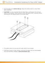
Installation Guidelines for Piezo LEGS® Caliper • Turn the stage over, bottom side up. Adjust the bottom block to center Motor Base lengthwise. • • CAUTION! It is very important that the Motor Base is self aligned. Do not force motor in any direction. Insert screws (4 x M2) and tighten them crosswise without disturbing the self aligned position of the Motor Base. • The cables needs to be secured with cable relief (of your design). • • CAD files of motors in both versions, and mock-up stage units are downloadable from the PiezoMotor webpage: www.piezomotor.com
Open the catalog to page 11
Installation Guidelines for Piezo LEGS®Caliper More information about the Piezo LEGS Caliper is found in the product data sheet Visit our website for application examples, CAD files, videos and more... PiezoMotor Uppsala AB Telephone: +46 18 489 5000 [email protected]
Open the catalog to page 12All PiezoMotor AB catalogs and technical brochures
 LR23-50
2 Pages
 LR23-80
2 Pages
 PMD101 Technical Manual
42 Pages
 Analogue Driver PMCM31
4 Pages
 Microstepping Driver 206
2 Pages
 Piezo LEGS® Rotary Ø17mm
4 Pages
 PiezoMotor Brochure
8 Pages
 PMD101 - Microstep Driver
2 Pages
 Piezo LEGS Caliper 20N
4 Pages
 Piezo LEGS Rotary 50mNm
4 Pages
 Piezo LEGS Rotary 80Nmm
4 Pages
 Piezo LEGS Linear 6N
4 Pages
 Piezo LEGS Linear Twin-C 20N
4 Pages
 Piezo LEGS Linear Twin 20N
4 Pages
 Piezo LEGS WavePlate
4 Pages
 Piezo LEGS Linear Twin-C 40N
4 Pages
 Piezo LEGS® Rotary Ø17
4 Pages


- Electromotor
- DC electromotor
- Motor controller
- Stepper motor
- DC motor controller
- Stepper motor controller
- Motor with built-in encoder
- Multi-axis positioning controller
- Stainless steel motor
- DC motion controller
- Analog motor controller
- Single-axis motion controller
- Microstepping motor controller
- Positioning motion controller
- PID positioning controller
- Industrial motion controller
- Piezoelectric motor
- Piezoelectric motion controller
- Linear piezoelectric motor
- Non-magnetic piezoelectric motor