- Catalogs
- PiezoMotor AB
- Analogue Driver PMCM31
Analogue Driver PMCM31
1 /4Pages

Analogue Driver PMCM31
1 /4Pages
Catalog excerpts
Nanometer resolution Analog control Low power consumption Small size Quick Start 1. Important note before connecting terminals: ● +12V terminal is not overvoltage protected and should be within ±0.5 V. ● An signal should not exceed ±20 V. ● Rst signal should be open collector (active low). 2. Connect a Piezo LEGS to the motor connector on the PMCM31 front panel. The PMCM31 is a 1-axis analog driver for use with Piezo LEGS motors from PiezoMotor. The driver enables single digit nanometer positioning in combination with mm/s speeds. Functional principle 4. Connect a ±9.6 V adjustable voltage source to the The driver controls the Piezo LEGS motor by feeding waveform signals which elongates and bends each of the piezo drive legs. The waveforms are specially designed to make the motor drive legs perform a precise walking motion. The motion of the drive legs is transferred via friction contact to a linear rod or to a rotary disc. For each waveform cycle the Piezo LEGS motor will take steps, by definition called waveform-steps (wfm‑steps). The wfm‑step length is load dependant and also depends on the signal phase shift. With maximum phaseshift (90˚) the step size is in the range of a few micrometers for a linear Piezo LEGS motor. Rotary Piezo LEGS motors have their drive legs working on the perimeter of a drive disc. The wfm-step angle depends on the diameter of the rotary motor but is usually less than one milliradian. The maximum step length (and hence the speed) is reduced by internal phase shifting of the waveform signal, and fine positioning is performed through analog bending of the drive legs. The user of the PMCM31 driver will only need to change the control signal voltage level in order to go from full step size down to high precision positioning. stabilized 0.3 A power supply with an output voltage of 12 ±0.5 V. An and GND terminals. 5. At power on the driver checks the capacitance of the motor (phase 1). After this check, the LED is turned ON. If the LED remains OFF, please check the power supply. 6. The following error indication may occur: If LED starts blinking after power ON, this indicates that motor capacitance check failed, e.g. no motor is connected (or motor is broken). 7. After power ON the driver will wait until An=0 V in order to prevent motor motion if no external An signal is available. 8. Motor is now ready to run, varying the voltage of the An signal to create motion. For an An voltage level less than ±0.6 V the motion is extremely slow. Below ±0.3 V the motion is stopped. For voltage level above ±0.6 V the motor velocity is set according to figure 1. Positive voltages refer to forward motion.
Open the catalog to page 1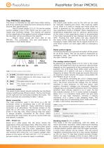
This driver is intended for use with Piezo LEGS motors, and driver outputs are designed not to stress the motors beyond their specifications. Use DC power supply (12 V, 0.3 A) and an analog control voltage (±9.6 V DC) which can be a part of a closed loop ontroller design. The velocity will depend c on the agnitude of the applied control voltage whereas m the direction will be according to the polarity. Picture below shows the front side of the PMCM31. The connectors, LED and push-button is described in more detail below. Reset button The brown push button next to the LED can be used for...
Open the catalog to page 2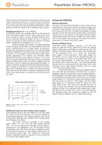
If the maximum bending range is exceeded, the driver will issue a “parking” equence, i.e. the drive leg is returned s to its center position, and hereafter continues to bend. t This may cause some minor positional fluctuation. After p arking, the driver starts with a relatively high velocity. Stepping mode 0.6 V < An < 9.6 V In stepping mode, the average velocity is governed by both cycle step length and the delay after each drive cycle. As seen in Figure 1. below, the step length is linear to An, reaching maximum length at ±8 V. A signal of ±9.6 V is enough to reach maximum velocity, whereas...
Open the catalog to page 3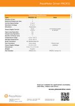
Technical Specification Type Electrical Phases per Axis Control Signal Range Waveform Voltage Power Supply Current Open Loop Operation Closed Loop Operation Number of Sensor Axis Temperature range Storage temperature at maximum speed at standby Motor Connector Port Connector Power Supply Voltage Dimensions Weight Part Number Phoenix type Visit our website for application examples, CAD files, videos and more... PiezoMotor Uppsala AB Stålgatan 14 SE-754 50 Uppsala, Sweden [email protected] www.piezomotor.com
Open the catalog to page 4All PiezoMotor AB catalogs and technical brochures
 LR23-50
2 Pages
 LR23-80
2 Pages
 PMD101 Technical Manual
42 Pages
 Microstepping Driver 206
2 Pages
 Piezo LEGS® Rotary Ø17mm
4 Pages
 PiezoMotor Brochure
8 Pages
 PMD101 - Microstep Driver
2 Pages
 Piezo LEGS Caliper 20N
4 Pages
 Piezo LEGS Rotary 50mNm
4 Pages
 Piezo LEGS Rotary 80Nmm
4 Pages
 Piezo LEGS Linear 6N
4 Pages
 Piezo LEGS Linear Twin-C 20N
4 Pages
 Piezo LEGS Linear Twin 20N
4 Pages
 Piezo LEGS WavePlate
4 Pages
 Piezo LEGS Linear Twin-C 40N
4 Pages
 Piezo LEGS® Rotary Ø17
4 Pages


- Electromotor
- DC electromotor
- Motor controller
- Stepper motor
- DC motor controller
- Stepper motor controller
- Motor with built-in encoder
- Multi-axis positioning controller
- Stainless steel motor
- DC motion controller
- Analog motor controller
- Single-axis motion controller
- Microstepping motor controller
- Positioning motion controller
- PID positioning controller
- Industrial motion controller
- Piezoelectric motor
- Piezoelectric motion controller
- Linear piezoelectric motor
- Non-magnetic piezoelectric motor