- Catalogs
- Philips Lumileds Lighting Company
- LUXEON® Rebel
LUXEON® Rebel

LUXEON® Rebel
The LUXEON Rebel General Purpose White Portfolio LEDs are designed for diverse lighting applications, known for high flux, color stability, excellent lumen maintenance, reliability, and quality white light.
Key Features
- High usable light and flux density.
- Optimized for reduced size and cost.
- Compatible with standard FR4 PCB and surface mount technology.
Product Nomenclature
Part numbers indicate radiation pattern, color, color variant, test current, and minimum luminous flux.
Average Lumen Maintenance
LEDs maintain 70% of initial light output after 50,000 hours at 700 mA, with a junction temperature at or below 135°C.
Environmental Compliance
Complies with RoHS directive, avoiding hazardous substances like lead and mercury.
Flux Characteristics
LEDs are binned based on flux performance with a Gaussian distribution, guaranteeing minimum luminous flux under specified conditions.
Optical Characteristics
Features a Lambertian beam pattern with typical viewing angles of 120 degrees, available in cool-white, neutral-white, and warm-white.
Electrical Characteristics
At 350 mA, forward voltage ranges from 2.55V to 3.99V, with typical thermal resistance of 10°C/W.
Absolute Maximum Ratings
- DC Forward Current: 1000 mA
- Junction Temperature: 150°C
- Operating Temperature: -40°C to 135°C
- Soldering Temperature: 260°C
Reflow Soldering Characteristics
Includes details on soldering profiles, ramp-up rates, and peak temperatures.
Mechanical Dimensions
Details package outline and pad configuration, emphasizing careful handling to avoid damage.
Solder Pad Design
Recommended PCB layout for optimal thermal resistance.
Wavelength Characteristics
Graphs illustrate spectral power distribution for cool-white and neutral-white LEDs.
Details thermal, electrical, and optical characteristics, including thermal pad temperature, spectral power distribution, and luminous flux across different temperatures and currents.
Procedures
Outlines testing procedures for luminous flux and forward current characteristics at a thermal pad temperature of 25°C, and describes current derating curves for different drive currents and ambient temperatures.
Norms and Standards
Adheres to binning and labeling standards for LED components, ensuring consistency in luminous flux, color, and forward voltage.
Recommendations
Provides recommendations for optimal mixing and matching of products using bin codes and maintaining specific thermal conditions for desired performance.
Key Data from Tables and Figures
- Figure 4c: Warm-white color spectrum.
- Figure 5: Relative luminous flux vs. thermal pad temperature.
- Figure 6: Forward current vs. forward voltage.
- Figure 7: Relative luminous flux vs. forward current.
- Figures 8-10: Current derating curves for various drive currents.
- Figures 11a and 11b: Typical spatial and polar radiation patterns.
- Tables 8-12: Luminous flux and forward voltage bins, color bin coordinates for different LED types.
Packaging and Binning
Describes emitter pocket tape and reel packaging, product binning and labeling methods, and the alphanumeric CAT code system for bin labeling.
Company Information
Philips Lumileds is a leading provider of power LEDs, focusing on advancing solid-state lighting technology, with R&D centers in the US and the Netherlands, and production facilities in multiple locations.
Catalog excerpts

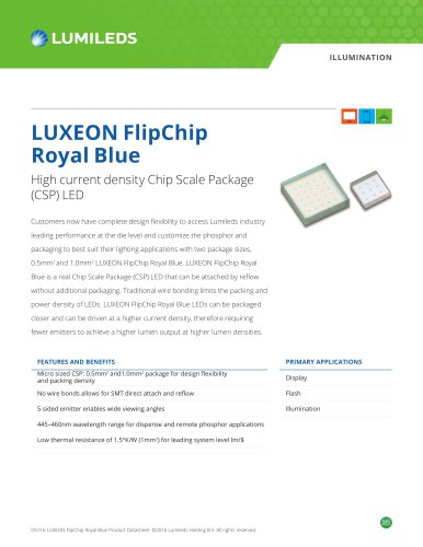
LUXEON Rebel General Purpose White Portfolio High fl ux and color stability Technical Datasheet DS64 Introduction The LUXEON® Rebel General Purpose White Portfolio LEDs in this datasheet are ideal for all lighting and illumination applications. These fl ux differentiated parts, like all other LUXEON Rebel LEDs, provide the industry’s best lumen maintenance, superior reliability and quality white light that make them the most widely used power LEDs today. Using the information in this document you can start designing applications to your unique specifi cations. LUXEON Rebel General Purpose White LEDs • Deliver more usable light and higher fl ux density • Optimize applications to reduce size and cost • Tightly pack the LEDs for mixing • Engineer more robust applications • Utilize standard FR4 PCB technology • Simplify manufacturing through the use of surface mount technology. LUXEON® Rebel General Purpose White Portfolio
Open the catalog to page 1
LUXEON Rebel General Purpose Datasheet DS64 (09/10/07) 3 Product Nomenclature LUXEON Rebel is tested and binned at 350 mA. The part number designation is explained as follows: L X M L - A B C D - E F G H Where: A — designates radiation pattern (value P for Lambertian) B — designates color (see LUXEON Rebel Binning and Labeling section) C — designates color variant (0 for direct colored variants) D — designates test current (value 1 for 350 mA) E — reserved for future product offerings FGH — minimum luminous fl ux (lm) or radiometric power (mW) performance Therefore products tested and binned...
Open the catalog to page 3
LUXEON Rebel General Purpose Datasheet DS64 (09/10/07) 4 Flux Characteristics for LUXEON Rebel, Thermal Pad Temperature=25°C Table 1. Performance at Test Current Typical Performance at Indicated Current Color Part Number Minimum Luminous Test Typical Luminous Drive Flux (lm) Current Flux (lm) Current ƒ¶V [1] (mA) ƒ¶V [2] (mA) LXML-PWC1-0040 40 350 80 700 LXML-PWC1-0050 50 350 95 700 LXML-PWC1-0080 80 350 145 700 LXML-PWC1-0090 90 350 160 700 LXML-PWC1-0100 100 350 180 700 LXML-PWN1-0040 40 350 80 700 LXML-PWN1-0050 50 350 95 700 LXML-PWN1-0080 80 350 145 700 LXML-PWN1-0090 90 350 160 700 LXML-PWN1-0100...
Open the catalog to page 4
LUXEON Rebel General Purpose Datasheet DS64 (09/10/07) 5 Flux Performance, Binning, and Supportability LEDs are produced with semiconductor technology that is subject to process variation, yielding a range of fl ux performance that is approximately Gaussian in nature. In order to provide customers with fi ne granularity within the overall fl ux distribution, Philips Lumileds separates LEDs into fi xed, easy to design with, minimum luminous fl ux bins. To verify supportability of parts chosen for your application design, please consult your Philips Lumileds/Future Lighting Solutions sales representative....
Open the catalog to page 5
LUXEON Rebel General Purpose Datasheet DS64 (09/10/07) 6 Lambertian LUXEON Rebel at Test Current [1] Thermal Pad Temperature = 25°C Table 2. Typical Total Typical Included Viewing Color Temperature [3] [4] Angle [5] Angle [6] CCT (degrees) (degrees) Color Min. Typ. Max. ƒå0.90V 2ƒå 1/2 Cool-White 4500K 6500K 10,000K 160 120 Neutral-White 3500K 4100K 4500K 160 120 Warm-White 2540K 3100K 3500K 160 120 Notes for Table 2: 1. Test current is 350 mA for all LXML-Pxx1-0xxx products. 2. CCT ±5% tester tolerance. 3. Typical CRI (Color Rendering Index) for cool-white is 70, neutral-white is 70 and warm-white...
Open the catalog to page 6
LUXEON Rebel General Purpose Datasheet DS64 (09/10/07) 7 Electrical Characteristics at 350 mA for LUXEON Rebel, Part Numbers LXML-Pxx1-0xxx, Thermal Pad Temperature = 25ºC Table 3. Typical Temperature Typical Thermal Coeffi cient of Resistance Forward Voltage Vf [1] Forward Voltage [2] Junction to (V) (mV/°C) Thermal Pad (°C/W) Color Min. Typ. Max. ƒ´Vf / ƒ´TJ Rƒå J-C Cool-White 2.55 3.15 3.99 -2.0 to -4.0 10 Neutral-White 2.55 3.15 3.99 -2.0 to -4.0 10 Warm-White 2.55 3.15 3.99 -2.0 to -4.0 10 Notes for Table 3: 1. Philips Lumileds maintains a tolerance of ±0.06V on forward voltage measurements....
Open the catalog to page 7
LUXEON Rebel General Purpose Datasheet DS64 (09/10/07) 8 Absolute Maximum Ratings Table 5. Parameter Cool-White/Neutral-White/Warm-White DC Forward Current (mA) 1000 Peak Pulsed Forward Current (mA) 1000 Average Forward Current (mA) 1000 ESD Sensitivity < 8000V Human Body Model (HBM) Class 2 JESD22-A114-B < 400V Machine Model (MM) Class 2 JESD22-A115-B LED Junction Temperature[1] 150°C Operating Case Temperature at 350 mA -40°C - 135°C Storage Temperature -40°C - 135°C Soldering Temperature JEDEC 020c 260°C Allowable Refl ow Cycles 3 Autoclave Conditions 121°C at 2 ATM 100% Relative Humidity...
Open the catalog to page 8
LUXEON Rebel General Purpose Datasheet DS64 (09/10/07) 9 Table 7. Profi le Feature Lead Free Assembly Average Ramp-Up Rate (Tsmax to Tp) 3°C / second max Preheat Temperature Min (Tsmin) 150°C Preheat Temperature Max (Tsmax) 200°C Preheat Time (tsmin to tsmax) 60 - 180 seconds Time Maintained Above Temperature TL (tL) 217°C Time Maintained Above Time (tL) 60 - 150 seconds Peak / Classifi cation Temperature (TP) 260°C Time Within 5°C of Actual Peak Temperature (tP) 20 - 40 seconds Ramp-Down Rate 6°C / second max Time 25°C to Peak Temperature 8 minutes max Note for Table 7: 1. All temperatures refer...
Open the catalog to page 9
LUXEON Rebel General Purpose Datasheet DS64 (09/10/07) 10 Mechanical Dimensions Figure 1. Package outline drawing. Notes for Figure 1: 1. Do not handle the device by the lens—care must be taken to avoid damage to the lens or the interior of the device that can be damaged by excessive force to the lens. 2. Drawings not to scale. 3. All dimensions are in millimeters. 4. The Thermal Pad is electrically isolated from the Anode and Cathode contact pads.
Open the catalog to page 10
LUXEON Rebel General Purpose Datasheet DS64 (09/10/07) 11 Pad Confi guration Note for Figure 2: 1. The Thermal Pad is electrically isolated from the Anode and Cathode contact pads. Solder Pad Design Note for Figure 3: The photograph below shows the recommended LUXEON Rebel layout on Printed Circuit Board (PCB). This design easily achieves a thermal resistance of 7K/W. Application Brief AB32 provides extensive details for this layout. In addition, the .dwg fi les are available upon request. Figure 2. Pad confi guration. Figure 3. Solder pad layout.
Open the catalog to page 11All Philips Lumileds Lighting Company catalogs and technical brochures
 LUXEON 5052 RGBW
20 Pages
 LUXEON Z Color Line
25 Pages
 LUXEON Rubix
41 Pages
 LUXEON FlipChip Royal Blue 2024
15 Pages
 LUXEON 3030 HE Plus
19 Pages
 LUXEON XR-5050 Round
13 Pages
 LUXEON XR-5050 HE
11 Pages
 LUXEON Mid-Power White LEDs
16 Pages
 LUXEON Color Portfolio
4 Pages
 LUXEON Altilon SMD
25 Pages
 LUXEON Neo
19 Pages
 Turn indicator
2 Pages
 Front fog
2 Pages
 Stop/tail
2 Pages
 DRL
DRL2 Pages
 SignalSure 75 Mid power solution
18 Pages
 SignalSure 30 Low power solution
16 Pages
 LUXEON R_2014-2015
19 Pages
 LUXEON FlipChip White
21 Pages
 LUXEON 5050
16 Pages
 LUXEON Rebel Color Line
31 Pages
 LUXEON XF-3014 CV
13 Pages
 LUXEON XR-M
14 Pages
 LUXEON 3030 HV
20 Pages
 LUXEON 3535L Line (Legacy)
25 Pages
 LUXEON XR-TX
9 Pages
 LUXEON HR30
18 Pages
 LUXEON CoB Core Range (Gen 3)
22 Pages
 LUXEON 2835 Line
22 Pages
 LUXEON XR-3020
10 Pages
 LUXEON CoB Compact Range (Gen 2)
17 Pages
 SnapLED Xtreme
15 Pages
 LUXEON F PC Amber
17 Pages
 Illumination Color Line Card
2 Pages
 Illumination Line Card
4 Pages
 LUXEON FlipChip UV
17 Pages
 LUXEON Z UV
15 Pages
 LUXEON M
23 Pages
 LUXEON MZ
22 Pages
 LUXEON Q
18 Pages
 LUXEON Rebel ES
33 Pages
 LUXEON Rebel
21 Pages
 LUXEON Rebel PLUS
17 Pages
 LUXEON TX
17 Pages
 LUXEON Z
17 Pages
 LUXEON Z ES
23 Pages
 LUXEON K
28 Pages
 LUXEON S
20 Pages
 LUXEON XF-3535L
18 Pages
 LUXEON 3014
18 Pages
 LUXEON 3020
20 Pages
 LUXEON 3535 2D
34 Pages
 LUXEON 3535 HV
21 Pages
 LUXEON 3535L
27 Pages
 LUXEON 4014
25 Pages
 SignalSure 250
15 Pages
 SnapLED 150
15 Pages
 LUXEON 3030 2D
19 Pages
 LUXEON Altilon
24 Pages


Archived catalogs
 Lamps Application Solutions
4 Pages
 LUXEON General Illumination
16 Pages
 LUXEON H 50-2
21 Pages
 LUXEON S2000, S3000, S5000
20 Pages
 LUXEON H 100/200
23 Pages
 LUXEON Z Color
28 Pages
 Lead-Free SuperFlux LEDs
17 Pages
 LUXEON C
17 Pages
 LUXEON R 2014
19 Pages
 LUXEON Rebel ANSI
33 Pages
 LUXEON XR-3535L
12 Pages
 LUXEON FlipChip
12 Pages
 LUXEON UV
15 Pages
 SuperFlux LEDs
14 Pages
 LUXEON T
16 Pages
 LUXEON Mid-Power 5630
28 Pages
 PB103LUXEON M
2 Pages
 LUXEON H - 100/200V
2 Pages
 LUXEON Rebel ES Blue
2 Pages
 LUXEON Products
2 Pages
 LUXEON A Datasheet
24 Pages
 LUXEON C Power LED
18 Pages
 Technical Datasheet DS64
30 Pages
 Technical Datasheet DS61
35 Pages
 LUXEON H Datasheet
19 Pages
 Technical Datasheet DS63
34 Pages
 LUXEON FlipChip Royal Blue 2020
17 Pages
 2016 LUXEON C Color Line
29 Pages
 2023 LUXEON C Color Line
34 Pages
 LUXEON R_2012
2 Pages
 SnapLED 70
5 Pages
 Lead Free SuperFlux LEDs
9 Pages
 LUXEON® Rebel ES
25 Pages
 LUXEON K2 Datasheet
41 Pages


