U3 Servo Motors

U3 Servo Motors
1 / 64 PagesView full catalog

U3 Servo Motors

Product catalog summary
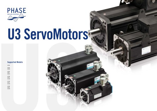
Overview: The U3 ServoMotor series by Phase Motion Control offers a variety of brushless PM AC servomotors designed for high dynamic control systems. These motors are available in different sizes with continuous torque ranging from 3 Nm to 1500 Nm and come in air-cooled, fan-cooled, and water-cooled versions.
Specifications: The motors feature a minimal inertia rotor for fast dynamic response, with options for additional inertia or a flywheel. They include a round shaft for clamping with conical hubs, and an optional key can be provided. The motors are equipped with a PM safety brake using rare earth permanent magnets, eliminating brake pads and reducing pollution risks.
Design and Protection: The motors have a single-piece extruded frame with IP65 protection (IP54 for fan-cooled versions), suitable for food and chemical applications. They include standard circular connectors and high flexibility cables, with position feedback sensors like Heidenhain absolute magnetic encoders and optional sinusoidal optical encoders or resolvers.
Technical Features: The U3 series uses sintered high-temperature rare earth magnets and features Class F motor insulation and Class H winding insulation. Thermal protection is provided by PTC 130 and KTY 84-130 or PT 1000 sensors. The motors are balanced to G 6.3 standards, with G 2.5 available on request.
Cooling and Sensors: Cooling options include natural, fan, and water cooling. Various sensors are available, including ENDAT and resolver types, with minimized EMC impact due to reduced stray capacitance.
Performance and Connections: The motors offer high torque density and low rotor inertia, with heavy-duty, life-lubricated bearings. Power connections vary by motor size, with specific configurations for signal and power connectors. Wiring recommendations include shielded cables and series inductance for long power cables.
Performance Curves and Ratings: The document includes performance curves for overload rating and thermal derating, with detailed specifications for each motor model, including rated speed, stall torque, rated power, and efficiency.
Ordering Information: The document provides detailed ordering codes for customization, including options for position sensors, brakes, connectors, thermal sensors, and shaft configurations.
Specifications: The document provides detailed specifications for U313 and U318 series servo motors, including efficiency, knee speed, maximum torque, current, and mechanical speed. It outlines the mechanical data such as inertia and mass, and technical data for holding brakes.
Procedures: Test conditions are specified, including water inlet temperature and chopper frequency requirements. The document also details the ordering code and options for customization, such as position sensors, brakes, connectors, and thermal sensors.
Standards and Norms: The document references DIN standards for shaft dimensions and mechanical coupling, emphasizing the importance of rigid mechanical coupling and high angular stiffness joints.
Recommendations: Application guidelines suggest replacing conventional motors with brushless drives for improved performance. It advises careful selection of system parameters and understanding the capabilities of brushless drive systems.
Key Data from Tables: Efficiency ranges from 86% to 97% across different models. Maximum torque values are specified for various models, with the highest being 3500 Nm. Knee speeds and maximum saturation speeds are provided for both 380Vac and 480Vac configurations.
Critical Information: Emphasizes the need for understanding new technology characteristics to avoid unexpected problems. It highlights the importance of selecting appropriate drive and mechanical linkage for optimal performance.
Introduction to Brushless Motors: Brushless motors are likened to loudspeakers due to their short response time and low inertia, which allows them to accurately follow control signals. The design of these systems requires an interdisciplinary approach, considering mechanical, electrical, and electronic factors.
System Design Considerations: Key design choices include mechanical linkages, transmission ratios, and electronic feedback strategies. The system's performance is influenced by the quality of sensors and the control algorithm.
Operational Principles: Brushless servo systems consist of an electronic drive, a servo motor, and feedback sensors. These components operate in a control loop to maintain desired motion characteristics, such as constant speed, by adjusting motor current based on sensor feedback.
Performance and Limitations: The speed accuracy of brushless drives is largely independent of the motor but depends on sensor quality and control algorithms. Mechanical linkages often limit system dynamics, and issues like noise and overheating can arise from mechanical inaccuracies rather than motor faults.
Design Optimization: Optimal drive design involves selecting appropriate transmission ratios and conversion types. Direct drive applications maximize control bandwidth and accuracy. Various transmission systems, such as timing belts and gear reducers, have different impacts on control bandwidth and system performance.
Application Classification: Applications are categorized into power services and position control. Power services focus on supplying power with less emphasis on dynamic performance, while position control requires precise and rapid movements.
Economic Considerations: For power services, economic optimization involves balancing motor and transmission costs. In dynamic applications, inertial matching can guide gear ratio selection, but it is not the sole consideration.
Motor and Gear Ratio Considerations: The document discusses the importance of selecting the appropriate transmission ratio for motors, emphasizing that a ratio based solely on the motor is flawed. It suggests that the best ratio should be equal to or less than the inertial ratio, considering both motor and reducer costs. High ratios can lead to reduced control bandwidth and accuracy, prompting a shift towards direct drives. For systems with high load inertia, achieving a high control bandwidth is crucial, requiring high-quality, stiff mechanical linkages without backlash.
Direct Drive and Torsional Stiffness: Direct drives necessitate checking the torsional stiffness of the system, especially for long and thin motors. The U3 Motor range offers options for both long, narrow motors for high acceleration with low inertia loads, and short, stocky motors for high inertia loads. The document provides formulas for calculating torsional stiffness and resonance frequency, advising checks on torsional resonance frequency for applications with large inertia and short settling times.
Control Strategy Selection: Three main control strategies are outlined: torque control, speed control, and position control. Torque control is the simplest and most robust, suitable for applications requiring force control. It requires minimal sensors and offers high stability. Speed control is traditional, while position control is used in digital drives for precise synchronization of multiple axes. The document suggests using torque control in multi-axis applications with modern NCs or controller boards for simplicity and cost-effectiveness.
Drive and Motor Sizing Verification: After selecting the motor and transmission, verifying the correct sizing is essential. For steady applications, checking the maximum load against motor and electronics limits suffices. For variable loads, a detailed process involving speed/time diagrams, inertia transfer, and torque calculations is necessary. The document provides a step-by-step guide for this verification process.
Motor Size Verification: Brushless motors are evaluated based on peak torque, thermal, and electric sizing. The document outlines checks for demagnetization current, temperature rise, and electric sizing to ensure the motor operates within acceptable limits. Excessive temperature rise is a primary reason for selecting a larger motor.
Worldwide Support and Distribution: The document concludes with contact information for Phase Motion Control's support and distribution network in France, Italy, Austria, and the USA.
See more

Catalog excerpts

U3 Servo Motors-3

U3 ServoMotor Series LEADING THE INNOVATION IN HIGH DYNAMIC AND TORQUE AND POSITION CONTROL FOR AUTOMATION U3 Servomotors are available in a wide size range with 6 flange sizes and continuous torque from 3 Nm to 1500 Nm. All sizes (except the smallest size 3) are available in Air Cooled, Fan Cooled and Water Cooled version. U3 Servomotors are designed for highly dynamic control systems. Consequently, motors are designed with minimal inertia rotor to allow fastest dynamic response. Additional inertia an extra flywheel can be introduced in the same brake cavity (as an alternative to brake) to compensate...

 Open the catalog to page 3

U3 Servo Motors-4

Phase Motion Control U3 Servomotors Brushless PM AC servomotors, low inertia, high angular stiffness. Type Brushless PM AC servomotors, low inertia, high angular stiffness. Rotor Sintered, high temperature rare earth, mechanically fastened magnets (without bonding). Insulation The U3 Motor Series of high performance servo motors, produced in the new Phase Motion Control plant specialized in high performance servo motors, is based on the last generation of rare earth magnets and embodies the patented Phase surface magnet assembly technology, which endows the motors with the highest torque density...

 Open the catalog to page 4
U3 Servo Motors-5

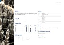
Heavy duty, life lubricated; Sizes 3 and 5; Sizes 7, 10, 13 and 18: front bearing locked in high strenght cast iron seat. Balancing G 6,3 (G 2,5 only on customer request). Cooling options Models U303 U305 U307 Shaft Cylindrical without keyway, tolerance j6, for interference mounting with shrink rings; axial threaded hole. Stray capacitance to ground Minimized EMC impact. Working position

 Open the catalog to page 5
U3 Servo Motors-6

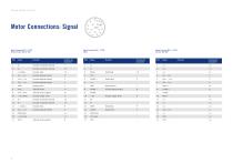
Phase Motion Control Motor Connections: Signal Signal Connector M23 - 17 PIN SinCos Encoder Type Sx*500 Signal Connector M23 - 17 PIN EnDat Signal Connector M23 - 17 PIN Resolver Type R09 Encoder incremental channel Encoder incremental channel Encoder index Endat data Endat clock Encoder absolute channel Encoder absolute channel Encoder absolute channel Supply ground Supply ground Thermal sensor Thermal sensor positive Thermal sensor negative Encoder incremental channel Encoder incremental channel Encoder index Endat data Endat clock Encoder absolute channel Thermal sensor positive

 Open the catalog to page 6
U3 Servo Motors-7

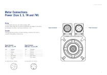
Motor Connections: Power (Size 3, 5, 7N and 7W) Wiring 1) Use shielded cable only, with shield coverage > 85% 2) Power cables longer than 20 meters may generate overvoltages on the motors and damage to the drives. Insert series inductance > 1mH Signal Connector Power Connector Encoder Phasing performed at factory, no further phasing is necessary if the motor is coupled to Phase Motion Control drives. Power Connector Power Connector For motors with Inom ≤ 30 Arms For motors with Inom > 30 Ar

 Open the catalog to page 7
U3 Servo Motors-8

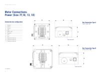
Phase Motion Control Motor Connections: Power (Size 7F,10, 13, 18) Connection box configuration

 Open the catalog to page 8
U3 Servo Motors-10

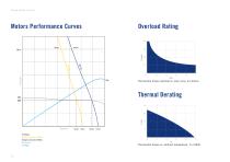
Phase Motion Control Motors Performance Curves Permissible torque overload vs. duty cycle, all motors. Thermal Derating Speed S1 Torque Voltage Saturation 380Vac Voltage Saturation 480Vac Max Torque S1 Power Permissible torque vs. ambient temperature, % of Md0

 Open the catalog to page 10
U3 Servo Motors-11

U303 Models Supported Models U303N

 Open the catalog to page 11
U3 Servo Motors-12

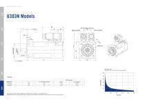
Phase Motion Control Max. Radial Load applicable in the middle of the shaft extension 1200 1000 A (1) (with brake or inertia) Shaft Dimensions MOTOR TYPE 1) Be carefully, with encoder: EQN1337; ECN1325 the total length is an additional 5mm. 2) Shaft dimension according to DIN 748-1 column (b): simultaneous transmission of torque and a known bending moment.

 Open the catalog to page 12
U3 Servo Motors-13

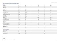
Natural Convection Cooling - For inverter rated Voltage 380Vac to 480Vac Motor Type Rated Speed Current @ Stall Torque 1) Nominal Rating Rated Torque 1) Rated Power Derating Temp. Coeff. Of Back EMF Nominal Voltage Minimum Flow Rate Knee Speed 380Vac and Mmax Knee Speed 480Vac and Mmax Max. Current (peak value) Mechanical Data (+/- 10%) Inertia Holding Torque Additional motor length Technical Data of the holding brake 3,8 24 Test Condition 1) Motor flanged on heatsink 300x300x20; Chopper frequency 8kHz

 Open the catalog to page 13
U3 Servo Motors-14

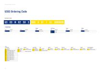
Phase Motion Control U303 Ordering Code Example Code Stall Torque Natural cooling Option Position Sensor Thermal Sensor Base Plate Motor Color Custom Documentation STD Black rear cover Blu STD Nameplate Right side STD Phasing/ Test report ACCORDING TO MOTOR DATA

 Open the catalog to page 14
U3 Servo Motors-15

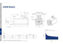
U305 Models Supported Models U305N U305W

 Open the catalog to page 15
U3 Servo Motors-16

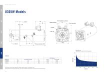
Phase Motion Control Max. Radial Load applicable in the middle of the shaft extension 2000 Shaft Dimensions MOTOR TYPE A (1) (with brake or inertia) 0 1) Be carefully, with encoder: EQN1337; ECN1325 the total length is an additional 5mm. 2) Shaft dimension according to DIN 748-1 column (b): simultaneous transmission of torque and a know bending moment.

 Open the catalog to page 16
U3 Servo Motors-17

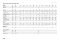
Natural Convection Cooling - For inverter rated Voltage 380Vac to 480Vac Motor Type Rated Speed Current @ Stall Torque 1) Nominal Rating Rated Torque 1) Rated Power Derating Temp. Coeff. Of Back EMF Nominal Voltage Minimum Flow Rate Knee Speed 380Vac and Mmax Knee Speed 480Vac and Mmax Maximum Values Max. Torque Max. Current (peak value) Mechanical Data (+/- 10%) Inertia Holding Torque Additional motor length Technical Data of the holding brake Test Condition 1) Motor flanged on heatsink 300x300x20; Chopper frequency 8kHz

 Open the catalog to page 17
U3 Servo Motors-18

Phase Motion Control Max. Radial Load applicable in the middle of the shaft extension 2000 Shaft Dimensions MOTOR TYPE A (1) (with brake or inertiaw) 0 1) Be carefully, with encoder: EQN1337; ECN1325 the total length is an additional 5mm. 2) Shaft dimension according to DIN 748-1 column (b): simultaneous transmission of torque and a know bending moment.

 Open the catalog to page 18
U3 Servo Motors-19

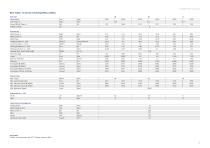
Water Cooling - For inverter rated Voltage 380Vac to 480Vac Motor Type Rated Speed Current @ Stall Torque 1) Nominal Rating Rated Torque 1) Rated Power Derating Temp. Coeff. Of Back EMF Nominal Voltage Minimum Flow Rate Knee Speed 380Vac and Mmax Knee Speed 480Vac and Mmax Max. Current (peak value) Holding Torque Additional motor length Technical Data of the holding brake Test Condition 1) Water inlet temperature max 20°C; Chopper frequency 8kH

 Open the catalog to page 19
U3 Servo Motors-20

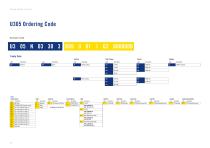
Phase Motion Control U305 Ordering Code Example Code Stall Torque Natural cooling Water cooling Option Position Sensor Thermal Sensor Base Plate Motor Color Custom Documentation description description STD Black rear cover Blu STD Nameplate Right side STD Phasing/ Test report ACCORDING TO MOTOR DATA KEY 6x6x28 and G1 Shaft Only available for: N03, N06, N09 KEY 8x7x32 and G2 Shaft Only available for: N12, W06, W09, W12

 Open the catalog to page 20

All Phase Motion Control catalogs and technical brochures
  1. AxN Drives

    24  Pages

  2. AxN Size 5

    1  Page

  3. AxN Size 4

    1  Page

  4. AXS 500

    3  Pages

  5. Axs-500

    3  Pages

*Prices are pre-tax. They exclude delivery charges and customs duties and do not include additional charges for installation or activation options. Prices are indicative only and may vary by country, with changes to the cost of raw materials and exchange rates.
About DirectIndustry
DirectIndustry is a marketplace that offers B2B players a complete experience, from product sourcing to purchase. DirectIndustry is an entity of VirtualExpo Group.