- Catalogs
- Phase Motion Control
- AxN Drives
- Company
- Products
- Catalogs
- News & Trends
- Exhibitions
AxN Drives
1 /24Pages

AxN Drives
1 /24Pages
Catalog excerpts

PHASE MOTION CONTROL Supported Models Size 2
Open the catalog to page 1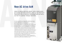
New AC drive AxN NEW AC DRIVE AXN HAS BEEN 100% DEVELOPED BY PHASE MOTION CONTROL AND IS THE PERFECT PARTNER FOR U3 SERIES SERVOMOTORS AS WELL AS FOR TK SERIES TORQUE MOTORS. AxN means a complete current range between 15 Arms and 110 Arms in 4 sizes, together with several interfaces: analogue (+/-10V), fieldbus (CANOpen and EtherCAT), pulse and direction. AxN is featuring a complete set of analogue and digital I/Os and a multiport encoder interface for the most common digital protocols (EnDat, Hiperface) as SinCos, TTL or resolver. Basic concepts behind AxN are: robustness (all internal components...
Open the catalog to page 3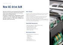
Phase Motion Control New AC drive AxN New AC drive AxN has been developed by Phase Motion Control and is the perfect partner for U3 brushless motors and for TK torque motors. AxN means a complete power range between 15 Arms to 200 Arms in 4 sizes, together with several built in interface: analogue (+/-10V), fieldbus (CANOpen and EtherCAT), pulse and direction. Basic concepts Robustness: all internal components are soldered and all the connectors have been designed in order to stand even the worst environmental conditions in terms of vibrations and mechanical stresses. Flexibility: mounting possible...
Open the catalog to page 4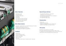
General Purpose Interface » Nr.2 programmable differential / 4 single ended analog input ± 10 V (1mV resolution) » Nr.2 programmable analog outputs 0-10V (1mV resolution) » Nr.8 programmable digital inputs » Nr.4 programmable digital outputs Profile position mode Profile velocity mode Interpolated position Mode Torque Mode Homing mode Cyclic Synchronous Position mode (CSP) Cyclic Synchronous Velocity mode (CSV) Cyclic Synchronous Torque mode (CST) Field Weakening Capability Main software features » » » » Internal PLC – LogicLab IEC61131-3 Integrated Development Enviroment. Configuration and control...
Open the catalog to page 5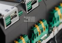
Phase Motion Control New design power connector Easy wiring connection Higher robustness Multiple ground connections
Open the catalog to page 6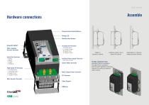
Hardware connections Assemble EtherCAT IN/OUT CAN / Auxiliary Encoder Terminals High Speed I/0 Terminals » 4 Analog Input » 2 Analog Output » 8 Digital Input » 4 Digital Output Main Encoder Terminals Tf\rr\ ri\ai Programmable Display Module Debug LED Multifunction Buttons » 3 Analog Input » 2 Analog Output » 8 Digital Input » 2 Digital Output Auxiliary Power Supply Terminals System Relay Terminals Motor Output Power Terminals PE Terminals Cable Support Totally in electrical cabinet Heatsink system out of electrical cabinet Flexible Installation Form Standard Cabinet Installation Through Panel...
Open the catalog to page 7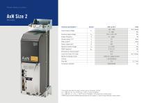
Phase Motion Control AxN Size 2 Technical specifications (1) Symbol AxN 15.30.4 Units (1) Test performed with full option control card and firmware 1.8.197 (3) V, = 380 Vac, I— = /, Tamb = 40°C, Comm.Freq.8kHz, Including input rectifier losses (4) PWM frequency will automatically decrease at Zero speed, in order to keep Nominal current output
Open the catalog to page 8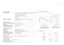
Motor Feedback Options Hardware Configuration Processor speed: 80 MIPS pC + FPGA / 120 MIPS pC + FPGA Extreme Version (Optional) Task frequency: » Current /drive monitoring: 1 MHz » Position/speed loop: 8 kHz » PLC fast task: 8 kHz » PLC slow task: 15.625 Hz to 1 kHz user-programmable Position loop mode available Target position register: 32 or 64 bits Full digital control Id/Iq, updated 16 kHz
Open the catalog to page 9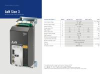
Technical specifications (1) Symbol AxN 22.44.4 AxN 35.70.4 AxN 50.100.4 Units (1) Test performed with full option control card and firmware 1.8.197 (3) vn = 380 Vac, iout = /, Tamb = 40°C, Comm.Freq.8kHz, Including input rectifier losses (4) PWM frequency will automatically decrease at Zero speed, in order to keep Nominal current output
Open the catalog to page 10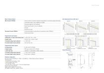
Motor Feedback Options Hardware Configuration Processor speed: 80 MIPS pC + FPGA / 120 MIPS pC + FPGA Extreme Version (Optional) Task frequency: » Current /drive monitoring: 1 MHz » Position/speed loop: 8 kHz » PLC fast task: 8 kHz » PLC slow task: 15.625 Hz to 1 kHz user-programmable Position loop mode available Target position register: 32 or 64 bits Full digital control Id/Iq, updated 16 kHz
Open the catalog to page 11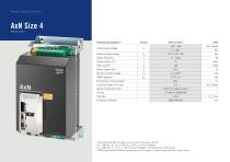
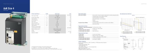
Phase Motion Control Technical specifications (1) Symbol AxN 70.140.4 Units (1) Test performed with full option control card and firmware 1.8.197 (3) Vin = 380 Vac, Iuut = In, Tamb= 40°C, Comm.Freq.8kHz, Including input rectifier losses (4) PWM frequency will automatically decrease at Zero speed, in order to keep Nominal current output
Open the catalog to page 12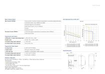
Motor Feedback Options Hardware Configuration Processor speed: 80 MIPS pC + FPGA / 120 MIPS pC + FPGA Extreme Version (Optional) Task frequency: » Current /drive monitoring: 1 MHz » Position/speed loop: 8 kHz » PLC fast task: 8 kHz » PLC slow task: 15.625 Hz to 1 kHz user-programmable Position loop mode available Target position register: 32 or 64 bits Full digital control Id/Iq, updated 16 kHz
Open the catalog to page 13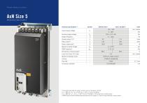
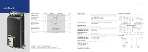
Phase Motion Control Technical specifications (1) Symbol AxN 90.150.4 AxN 110.200.4 Units (1) Test performed with full option control card and firmware 1.8.197 (3) V.n = 380 Vac, Iuut = I, Tamb= 40°C, Comm.Freq.8kHz, Including input rectifier losses (4) PWM frequency will automatically decrease at Zero speed, in order to keep Nominal current output
Open the catalog to page 14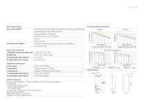
Motor Feedback Options Hardware Configuration Processor speed: 80 MIPS pC + FPGA / 120 MIPS pC + FPGA Extreme Version (Optional) Task frequency: » Current /drive monitoring: 1 MHz » Position/speed loop: 8 kHz » PLC fast task: 8 kHz » PLC slow task: 15.625 Hz to 1 kHz user-programmable Position loop mode available Target position register: 32 or 64 bits Full digital control Id/Iq, updated 16 kHz
Open the catalog to page 15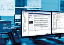
Installation, Configuration and Control Tool for Programmable Motion Control Platforms. 0 Target info K P All parameters B P Core f* Motor It) f Incoder B P Absolute Analogue Traces B p HallsensorsTrates B (5 Incremental I races W P Sensorless P llertncal field Onoitatron B P Mender : E 0 Aualiaiy P Incremental Traces P Monitor p Monitor B P Torque Loop E P Speed Pos Loop B P DevreeControl B p Fieldbus M P System B £\ Alarms App'if Jtion Se'ection App'icatioo Configuration £3 Monitor page ^ Feedback encoder £3 Motor |P Brake unit ^ Space Speed Control Loop Q Motion Control Application _Q CANOpen...
Open the catalog to page 16All Phase Motion Control catalogs and technical brochures
 AxN Size 5
1 Page
 AxN Size 4
1 Page
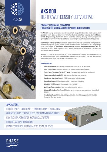 AXS 500
3 Pages
 Axs-500
3 Pages
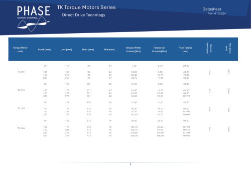 Tk Datasheet Catalog
5 Pages
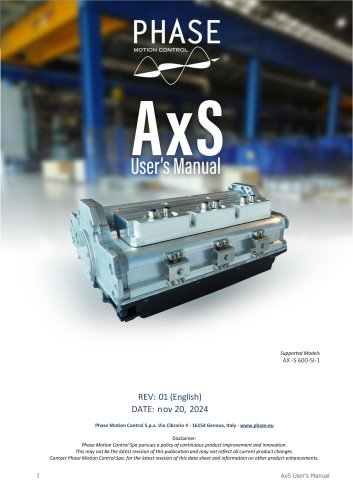 Axs EV Ruggedized Servo Drive
17 Pages
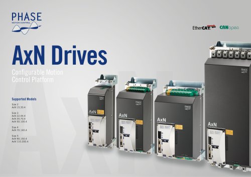 Axn Drive Catague
24 Pages
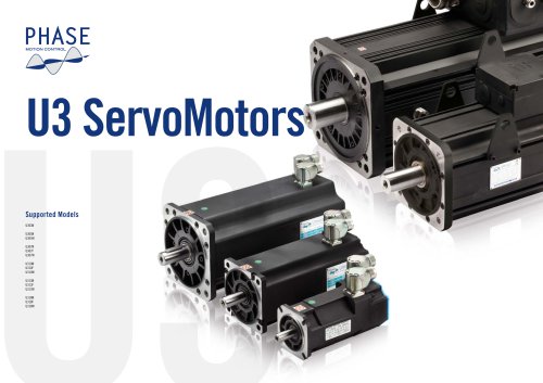 U3 Servo Motors
64 Pages
 PX Power Supply Unit - 4 KW
6 Pages
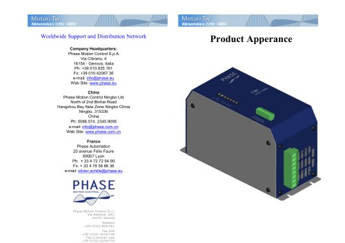
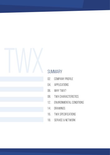 TWX - Integrated Servo Motor
11 Pages

- DC power supply
- AC/DC power supply
- Single-output power supply
- Power supply for industrial applications
- Power supply with overload protection
- Servo-amplifier
- AC servo-motor
- High-performance servo motor
- Single-phase power supply
- DC servo-amplifier
- Fieldbus servo-drive
- Multipole servomotor
- IP65 servomotor
- DC servo-motor
- Controller servomotor
- Ultra-compact servomotor
- BLDC servomotor
- AC servo-amplifier