
- Catalogs
- PETER HIRT GmbH
- Transducer

Transducer

Transducer
This section provides a comprehensive list of transducers offered by PETER HIRT GmbH, detailing various models such as T071/T072, T101/T102, and others. Each model is described with its specific features like measuring stroke, compatibility (e.g., TESA® compatible), and configurations (axial, radial).
Key terms related to transducers are defined, including pretravel, linearity error, and repeatability. The glossary explains the importance of these terms in the context of transducer performance and measurement accuracy.
This section provides instructions for qualified personnel on mounting, changing tips, setting pretravel, and maintaining transducers. It emphasizes the importance of using original parts and following proper procedures to ensure accurate measurements.
Details on digital transducers with integrated electronics and interface connections are provided. The section explains the communication protocol used for data transfer and the importance of conditioning electronics in processing sensor signals.
Each transducer model is specified with its measuring stroke, compatibility, and application pressure limits. Procedures for changing components like tips and bellows are outlined to maintain transducer functionality.
The document references DIN ISO 2768-1 for general tolerances in length measurements, ensuring precision and standardization in manufacturing and application.
The document provides technical specifications and data for various transducer models, including T161/T162, T201/T202, T301/T302, T401/T402, and T501/T502. Each model is detailed with its unique features, specifications, and operational parameters.
- Transducer Models: T161/T162, T201/T202, T301/T302, T401/T402, T501/T502.
- Maximum Stroke: Varies by model, with T161/T162 and T301/T302 having a maximum stroke of 4.6 mm, while T201/T202 has 2.5 mm.
- Measuring Stroke: Typically ±1 mm or ±2 mm depending on the model.
- Repeatability: Generally 0.01 µm for most models, ensuring high precision.
- Linearity Error: Ranges from 0.25% FS to 0.6% FS across different models.
- Sensitivity: Varies, with values such as 230 mV/(Vmm) for T161/T162 and 73.75 mV/(Vmm) for T201/T202.
- Drive Frequency: Typically around 13 kHz to 20 kHz, depending on the model.
- Supply Voltage: Commonly 3 V or 5 V ±0.5% RMS.
- Temperature Range: Operational range from -10 to +65 °C.
- Bearing: Ball bearing with no side-play, lapped for most models.
- Tip: Tungsten carbide ball, exchangeable, with sizes varying by model.
- Body Diameter: Consistently 8h6 across models.
- Cable: PUR, length 2 m, with 5 pin, 270° plug.
- Mounting Position: Flexible, can be mounted in any position.
- Repairability: Units can be disassembled for repair.
- Pressure and Spring Rate: Specific to pneumatic models, with maximum pressures up to 4.5 bar.
The document includes detailed diagrams and measurements for each transducer model, emphasizing the importance of precision and adaptability in various engineering applications. Errors and omissions are excepted, and specifications are subject to change without notice.
This document provides technical specifications for various transducer models, including T801/T802 and T851/T852, as well as additional models like 10P0/10P1/1P0 and T070/T100. These transducers are used for precise measurement applications and are characterized by their cable exit configurations, stroke capabilities, and other technical parameters.
- Cable Exit: Models T801 and T851 have axial exits, while T802 and T852 have radial exits. Similarly, 10P0 and 1P0 have axial exits, and 10P1 has a radial exit.
- Maximum Stroke: T801/T802 and T851/T852 have a maximum stroke of 6.0 mm, while 10P0/10P1 have 0.8 mm, and 1P0 has 1.2 mm. T070 and T100 models have strokes of 2.2 mm and 4.6 mm, respectively.
- Measuring Stroke: All models have a measuring stroke of ±1 mm, except for 10P0/10P1 (±0.25 mm) and 1P0 (±0.40 mm).
- Pretravel: Adjustable pretravel settings are available, with default settings varying slightly between models.
- Bearing: All models feature ball bearings with no side-play and are lapped for precision.
- Life Cycle: The transducers are designed for over 10 million cycles.
- Temperature Range: Operational and storage temperatures range from -10 to +65 °C.
- Mounting Position: All models can be mounted in any position.
- Repeatability and Linearity Error: Repeatability is 0.01 µm, with linearity errors ranging from 0.25% to 1.25% FS depending on the model.
- Sensitivity and Drive Frequency: Sensitivity varies slightly between models, with drive frequencies of 5 kHz or 13 kHz.
- Supply Voltage: All models operate at 3 V ±0.5% RMS.
- Repairability: Units can be disassembled for repair.
- Coil Form: Models are compatible with TESA® standards, with halfbridge and fullbridge configurations available.
The document references DIN ISO 2768-1 for general tolerances on length measurements, ensuring precision in manufacturing and application.
The document provides detailed technical specifications and application information for various bore measuring transducers and related signal conditioning modules. It includes data on the BMT200 and BMT500 transducers, signal conditioning modules, and digital transducers.
- BMT200: Maximum stroke of 0.6 mm, measuring stroke of ±0.2 mm, life expectancy of over 10 million cycles, and a temperature range of -10 to +65 °C. It features a 3 mm tungsten carbide ball tip, FPM sleeve and sealing, and a halfbridge coil form compatible with TESA®.
- BMT500: Maximum stroke of 1.1 mm, measuring stroke of ±0.5 mm, similar life expectancy and temperature range as BMT200, and uses a M3 helicoil for fixing.
- Cable Module: Provides signal conditioning for T-series transducers with output signals of ±10 VDC or ±5 VDC. It supports various supply voltages and has a dimension of 73.5 x 51 x 25 mm.
- DIN-Rail Module: Similar functionality as the cable module but designed for DIN rail mounting with dimensions of 86 x 35 x 57.5 mm.
- These transducers are designed for connection to compatible interface converters and electronics, featuring an inductive halfbridge coil system with integrated conditioning electronics. They support various communication protocols including IO-Link for PLC systems.
The document provides examples for ordering different configurations of transducers and modules, specifying parameters such as supply voltage, signal output, and measuring stroke.
The document includes details on the MICRON switch, a small signal switch with high repeatability, and various digital transducer models with different configurations for specific applications.
The document provides detailed technical specifications for the T100 and T500 series digital transducers. Both series feature models with a maximum stroke of 4.6 mm for T100 and 10.6 mm for T500, with measuring strokes of ±2 mm and ±5 mm respectively. All models use ball bearings with no side-play and are lapped for precision.
Both series operate within a temperature range of -10 to +65 °C, suitable for both storage and operation. The transducers can be mounted in any position.
The transducers feature a 3 mm tungsten carbide ball tip with an M2.5 fixing thread, which is exchangeable. The body diameter is consistent at 8h6 across all models, and they use a DIN M5 plug.
Repeatability is maintained at 0.02 µm for T100 and 0.05 µm for T500, with an error limit of ±1.0 µm and ±2.5 µm respectively at 20 °C ±1 °C. The measuring system is based on an inductive halfbridge.
All models support a communication protocol for digital HIRT transducers with a transfer rate of 4000 measurements per second. Power consumption is 5V, 120 mW during operation, and 15 mW when idle.
Some models include pneumatic advance and lift-off features, with maximum pressures of 1.5 bar and 4.5 bar for specific models. The spring rate varies slightly between models, with options available.
Repair is partially possible for all models, ensuring some level of serviceability.
The document also references general tolerances for length measurements according to DIN ISO 2768-1 standards, indicating precision levels for various nominal size ranges.
Catalog excerpts

Transducer PETER HIRT GmbH
Open the catalog to page 1
[email protected] www.peterhirt.com Some company registered trade names are used in this catalogue. They are used for reference only and have no relationship to PETER HIRT GmbH.
Open the catalog to page 3
PETER HIRT GmbH Errors and omissions excepted, subject to change without notice
Open the catalog to page 4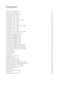
User Guide for Transducers 10 Transducer pluggable T100 pig-tail 52 Transducer pluggable T500 pig-tail 56 Bore measuring transducer BMT200 60 Bore measuring transducer BMT500 62 Interface Digital Transducer to USB 80 Connection cable for digital transducers 81 Digital Transducer IO-Link T100 82 Digital Transducer IO-Link T500 86 Cables / Connection cables 92
Open the catalog to page 5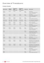
PETER HIRT GmbH Errors and omissions excepted, subject to change without notice
Open the catalog to page 6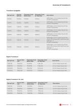
Transducer pluggable PETER HIRT GmbH 7 Errors and omissions excepted, subject to change without notice
Open the catalog to page 7
All transducers in this catalogue are drawn in «electrical zero» position. The stated pre-travel indicates the transducer position without applied vaccum or pneumatic pressure. The transducer T101F, drawn below is in «electrical zero» position and has -1.2 mm pre-travel and a total mechanical stroke of 4.6 mm. 1:1 Is the deviation between the sensor signal and the real mechanical position of the tip. Stated errorsFormat are Geprüft/Freig. Material: Gewicht: 0.02 kg Rohmass: Status: Behandlung: always relative to the stroke. Each manufactured transducer is delivered with a measuring protocol..A4...
Open the catalog to page 8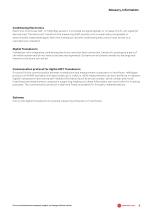
Glossary, Information Conditioning Electronics Electronic to process half- or fullbridge sensors. It provides its signal digitally or on base of a SI-unit signal (or derived one). The electronic transfrom the measuring shaft position into a numerically processable or electronically measurable signal. Both the transducer and the conditioning electronics must be set to a manufacturer standard.. Digital Transducers Transducer with integrated conditioning electronic and interface connection. Sensitivity settings are part of the whole system and do not need to be assured seperately. Systems errors...
Open the catalog to page 9
Introduction These products are intended to be used by qualified personnel only. Mounting the transducers The transducer may be clamped over the full length of the case. Do not over clamp and ensure free movement of the linear bearing. Select an appropriate clamping element which does not deform the case. Change tip (except 10PO, 10P1 and T200 series) The tip will be firmly tightened to ensure correct results. To change the tip -Slip the bellow (3) with small bellow ring (2) back up the shaft until the key flats become usable -Use the supplied key (small opening) on the shaft key flats - never...
Open the catalog to page 10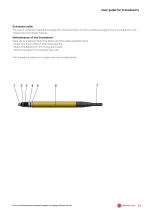
User guide for transducers Extension cable The use of extension cables do change the characteristics of the transducer and are to be considered in the measuring uncertainty figures. Maintainance of the transducer Keep the transducer body, the bellow and the cable assembly clean -Check the free rolling of the linear bearing -Check the bellow for firm fixing and cracks -Check the cable for scratches and cuts 3 Geändert Gewicht: The transducer does not contain user serviceable parts. Errors and omissions excepted, subject to change without notice
Open the catalog to page 11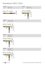
Spring push cable exit axial Vacuum retract cable exit radial 18.9 push 5cable exit radial Pneumatic push bellow seal cable exit radial 31.4 18.9 meintoleranzen für Längenmasse emeintoleranzen für Längenmasse Pneumatic push air 18.9 31.4 gap seal cable exit radial 31.4 18.9 Änderung: Klassifizierung: Material: Gewicht: 0.01 kg Änderung: Klassifizierung: Rohmass: Behandlung: Material: Gewicht: 0.01 kg Errors and omissions excepted, subject to change without notice Benennung: Rohmass: Behandlung: Klassi Erste Klas Geä Erst Gewic Gep Gew Geä Erstel Rohm Roh Statu Gep Geän
Open the catalog to page 12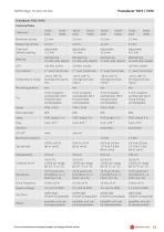
Transducer T071 / T072 Transducer T071/T072 Technical Data Errors and omissions excepted, subject to change without notice
Open the catalog to page 13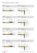
Errors and omissions excepted, subject to change without notice 14 PETER HIRT GmbH
Open the catalog to page 14
Transducer T101 / T102 TransducerT101/T102 Technical Data Errors and omissions excepted, subject to change without notice
Open the catalog to page 15
1001303 Pneumatic push air gap seal T151L cable exit axial 1001319 Pneumatic push air gap seal T152L cable exit radial
Open the catalog to page 16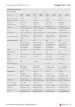
Transducer T151 / T152 TransducerT151/T152 Technical Data Errors and omissions excepted, subject to change without notice PETER HIRT GmbH 17
Open the catalog to page 17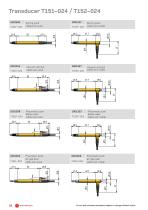
18 PETER HIRT GmbH Errors and omissions excepted, subject to change without notice
Open the catalog to page 18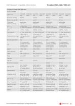
Transducer T151-024 / T152-024 Transducer T151-024/T152-024 Technical Data Errors and omissions excepted, subject to change without notice peter hirt GmbH 19
Open the catalog to page 19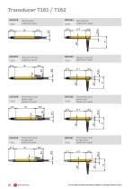
2 0 PETER HIRT GmbH Errors and omissions excepted, subject to change without notice
Open the catalog to page 20
Transducer T161 / T162 TransducerT161/162 Technical Data Errors and omissions excepted, subject to change without notice peter hirt GmbH 21
Open the catalog to page 21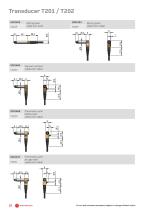
Spring push cable exit radial Pneumatic push bellow seal 9 cable exit radial 9 3 Spring push cable exit axial 9 Pneumatic push air gap seal cable exit radial 9 Errors and omissions excepted, subject to change without notice
Open the catalog to page 22
Transducer T201 / T202 Transducer T201/T202 Technical Data Errors and omissions excepted, subject to change without notice
Open the catalog to page 23
1001562 Pneumatic push bellow seal T301p cable exit axial 1001634 Pneumatic push bellow seal T3°2p cable exit radial 1001544 Pneumatic push air gap seal T301L cable exit axial 1001617 Pneumatic push air gap seal T302L cable exit radial Errors and omissions excepted, subject to change without notice
Open the catalog to page 24
Transducer T301 / T302 TransducerT301/T302 Technical Data Errors and omissions excepted, subject to change without notice
Open the catalog to page 25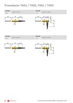
cable exit radial cable exit axial Errors and omissions excepted, subject to change without notice
Open the catalog to page 26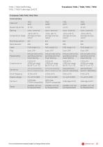
peter hirt GmbH 27 Errors and omissions excepted, subject to change
Open the catalog to page 27
1001778 Pneumatic push bellow seal T501p cable exit axial 1001860 Pneumatic push bellow seal T502P cable exit radial 2 8 PETER HIRT GmbH Errors and omissions excepted, subject to change without notice
Open the catalog to page 28All PETER HIRT GmbH catalogs and technical brochures
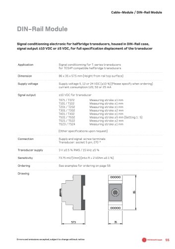 DIN-Rail Module
2 Pages
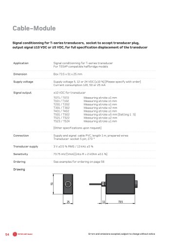 Cable-Module
2 Pages
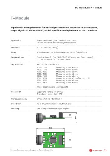 T- M o d u l e
2 Pages
 ManualHalfbridge Transducer
19 Pages

- Rectangular housing
- Data logger
- USB datalogger
- Electronic equipment enclosure
- Compact housing
- Datalogger without display
- Displacement transducer
- Linear displacement sensor
- Signal conditioner
- Touch probe
- Analog displacement transducer
- Stainless steel housing
- Industrial displacement sensor
- Measurement touch probe
- Lockable enclosure
- Precision displacement sensor
- Compact displacement sensor
- Analog signal conditioner
- Rugged displacement sensor
- DIN rail signal conditioner