- Catalogs
- Pertronic Industries Pty Ltd
- CP500 HANDHOLD PROGRAMMER
CP500 HANDHOLD PROGRAMMER
1 /1Page
CP500 HANDHOLD PROGRAMMER
1 /1Page
Catalog excerpts
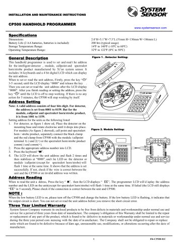
INSTALLATION AND MAINTENANCE INSTRUCTIONS CP500 HANDHOLD PROGRAMMER www.systemsensor.com Dimensions: Battery Life (2 AA batteries, batteries is included): Storage Temperature Range: Operating Temperature Range: General Description This handhold programmer is used t o set and read t he address for the intelligent detector , module, callpoint and spectralert horn/strobe product manufactured by Xi’an system sensor. It includes 16 keyboards and a 4 bit digital LCD which can display the unit address. When to set or read the unit address, Firstly, press the key “ ” 3-5 second, until the LCD display “0000” and release the key . Then you can set or read the unit address after the LCD display “0000”. After you finish reading or setting the address, press the key “ ” until the LCD is off to stop working. If there is no any action for 5 minutes, the CP500 will stop working by itself. Address Setting Note: A valid address consists of four bits digit. For detector, the address is set from 0001 to 0159. But for the module, callpoint and spectralert horn/strobe product, it is from 1001 to 1159. Setting address for the units as the following listed: 1. For detector, as figure 1 show ed, Place the detector on the mounting base and rotate clockwise until it drops into place. For module (As figure 2 showed), call point and spectralert horn / strobe product, separately connect the black clamp and the red clamp from CP500 with the module /callpoint terminal 1(-) and 2(+) or the spectralert horn/strobe product comm(-) and comm(+). 2. Press the appropriate address number into LCD. 3. Press the keyboard “W”. 4. The LCD will sh ow the unit address and flash 2 times and then stabilizes at “0000”, and t he LED on the detector or module /callpoint (except for spectralert horn/strobe) will flash 1 time at the same time. It shows that the address is set successfully. If not, check if the wire is correct between the unit and the CP500 or an invalid address was written. Figure 2. Module Setting: Address Reading When to read the unit a ddress, Press the key “ R”, then the LCD displays “ EE”, The programmer LCD will d isplay the address number and the LED on the unit(except for spectralert horn/strobe) will flash 1 time at the same time. If failed (the LCD still displays “EE” in 5 second), Please check if the connection is correct between the unit and CP500. When the low battery LED is on, please turn off the CP500 and change the battery. If the low battery LED is flashing, it indicates that the output circuit is short. You can not set or read the unit address before you remove the short circuit error. Three Year Limited Warranty System Sensor Company warrants its enclosed products to be free from defects in materials and workmanship under normal use and service for a period of three years from date of manufacture. The company’s obligation of this Warranty shall be limited to the repair or replacement of any part of the product, which is found to be defective in materials or workmanship under normal use and service during the three year period com mencing with the date of m anufacture. The Company shall not be obligated to repair or replace units which are found to be defective because of dam age, unreasonable use, modifications, or alterations occurri
Open the catalog to page 1All Pertronic Industries Pty Ltd catalogs and technical brochures
 Outdoor Strobe SRHKRLFIRE
2 Pages
 PERTRONIC INDUSTRIES LTD
4 Pages

Archived catalogs
 B501AUS
2 Pages
 2251CTLE-34-IV
2 Pages
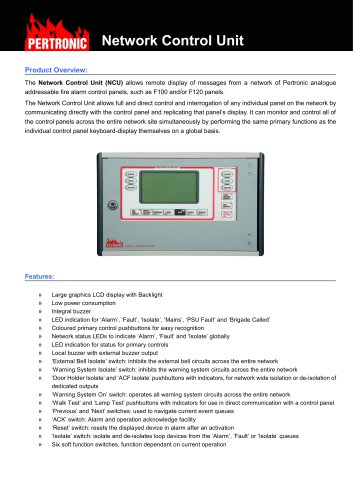 NETCU-A
2 Pages
 COPTIR
6 Pages
 5251RB-WP
2 Pages
 22051TLE-34
2 Pages
 2251BPI
2 Pages
 NETCARD
2 Pages
 F120A
F120A4 Pages
 Petronic F 220
2 Pages
 PTIR
PTIR6 Pages


- LIMING power supply
- LIMING DC power supply
- LIMING AC/DC power supply
- LIMING digital I/O
- LIMING Windows software
- Real-time software
- Computer-aided design software
- LIMING I/O module
- Single-output power supply
- Design software solution
- LIMING digital I/O module
- 3D software solution
- LIMING communication gateway
- LIMING interface software
- LIMING signal amplifier
- Visualization software solution
- LIMING Ethernet gateway
- Fieldbus gateway
- Serial gateway
- Modular housing