Catalog excerpts

Series Thermal Over-load Relay Usage and its scope of application JRS8 series (T series thermal relay) bimetal type thermal over-load relay is suitable for the power system of AC50Hz or 60Hz, rated operating voltage Ue: 660V, current 0.1~500A, as the use of over-load and break phase protection for AC motor. Thermal relay with the functions of break phase, temperature compensation, action indication, auto and manual reset, and stop, etc. This product confirms to: GB14048.4, IEC60947-4-1 etc. standards. Installation mode: Z for Combination type, F for separated type Code for specification (to be indicated as rated current) Design serial No. Three phase type Thermal Over-load Relay Normal operating condition and installation condition 3.1 Ambient temperature: -5℃~+40℃, average value within 24h does not exceed +35℃ 3.2 Altitude: does not exceed 2000m 3.3 Atmosphere condition: relatively humidity does not exceed 50% when at the highest temperature of +40℃; It allowed relatively high humidity when it is at relatively low temperature, average lowest temperature of the most wet month does not exceed +25℃, and the average maximum humidity of this month does not exceed 90%, and should be considered the condensation produced on the product due to the temperature variation. 3.4 It should be at the no explosion danger medium, and the medium without the gas that cannot corrode the metal and damage the insulation as well as the places that without conductive dust. 3.5 Grade of pollution: 3 3.6 Installation category: III 3.7 Installation position: installed at the normal position, the gradient between the installation side and the vertical side does not exceed ±5°, and without obvious vibration and impact. 3.8 Protection grade: IP 00 3.9 Installation mode a) Combination mode Put the conduct rod directly plug-in install at the terminal of relevant AC contactor, the combination mode is the basic type of installation for this series thermal relay. b) Separated mode To make the thermal relay be installed at relevant installation board first, and then to install the installation board by screw or make the installation board directly insert on the installation rail.
Open the catalog to page 1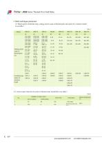
www.peopleelectric.com simon@chinapeople.com
Open the catalog to page 2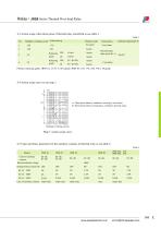
4.3 Action scope when three poles of thennal relay electrified to see table 3 www.peopleelectric.com simon@chinapeople.com
Open the catalog to page 3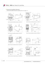
Series Thermal Over-load Relay External and installation dimension External and installation dimension of thermal relay to see map 2~12 Map 2 External and installation dimension for JRS8-16/Z Map 3 External and installation dimension for JRS8-16/F Map 4 External and installation dimension for JRS8-25/Z Map 5 External and installation dimension for JRS8-25/F Map 6 External and installation dimension for JRS8-45/Z Map 7 External and installation dimension for JRS8-45/F Map 8 External and installation dimension for JRS8-85/Z Map 9 External and installation dimension for JRS8-85/F
Open the catalog to page 4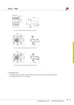
Map 10 External and installation dimension for JRS8-170 Map 11 External and installation dimension for JRS8-250 Map 12 External and installation dimension for JRS8-370 Ordering Notice It required to be noted: Product model, specification, setting current scope and required quantity For example: JRS8-45, 0.35~0.52, 200 pcs
Open the catalog to page 5All PEOPLE ELE. APPLIANCE GROUP CO. catalogs and technical brochures
-
DZ47-63
2 Pages
-
LXP1
2 Pages
-
RDQ1
6 Pages
-
WL Series Travel switch
2 Pages
-
RDLX18 Series Travel switch
3 Pages
-
RDD6 series indicator lamp
2 Pages
-
RDJR6 series soft-starter
7 Pages
-
RDI67 series inverter
3 Pages
-
RDR67 Series Relay
6 Pages
-
JRS2 Series Thermal Relay
5 Pages
-
RDC67 series AC contactor
3 Pages
-
CJX5 Series AC Contactor
3 Pages
-
RDC6 Series AC Contactor
4 Pages
-
CJX1 Series AC Contactor
4 Pages
-
RDSP6 serie surge arrester
2 Pages
-
RDB67LE-63 series RCBO
3 Pages
-
DZ47LE series RCBO
2 Pages
-
RDL67-63 series RCCB
2 Pages
-
RDL63E-63 series RCCB
2 Pages
-
RDX30LE-32
2 Pages
-
RDX65LE-63 series RCBO
2 Pages
-
RDX6LE-40
2 Pages
-
RDX6LE-63 series RCBO
2 Pages
-
RDB5-63 series MCB
1 Pages
-
RDX6-40 series MCB
2 Pages
-
RDB2-125S series MCB
2 Pages
-
RDX6-63DC series MCB
2 Pages
-
RDX30-32 series MCB
2 Pages
-
RDX65-63 series MCB
2 Pages
-
RDB2-125 series MCB
3 Pages
-
RDB67-63 series MCB
2 Pages
-
RDX2-125 series MCB
2 Pages
-
RDX6-63 series MCB
2 Pages
-
QZB series auto-transformer
2 Pages
-
RDW2-1600 series
13 Pages


