PT10
1 /2Pages

PT10
1 /2Pages
Catalog excerpts
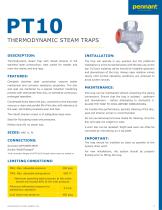
THERMODYNAMIC STEAM TRAPS DESCRIPTION: Thermodynamic steam trap with inbuilt strainer in full The trap will operate in any position but the preferred stainless steel construction, best suited for header and installation is in the horizontal plane with the disc cap on the main line drains and drip legs. top. Full port isolating valves should be installed upstream and downstream of the trap. Always open isolation valves FEATURES: Complete slowly until normal operating conditions are achieved to steel mechanical and corrosion resistance properties. The disc avoid system shocks. and seat are hardened by a special induction hardening process with seat harder than disc, to withstand continuous, This trap can be maintained without disturbing the piping prolonged operation. connections. Ensure that the trap is isolated - upstream Condensate entry below the disc, concentric to the disc/seat ensures a clean and parallel lift of the disc with reference to the seat, eliminating localized wear and tear. and downstream - before attempting to dismantle it. ALLOW THE TRAP TO COOL BEFORE DISMANTLING. For trouble-free performance, periodic cleaning of the disc, The inbuilt strainer screen is of adequately large area. seat and strainer screen is recommended. Do not use abrasive/corrosive media for cleaning. Only the Ideal for fluctuating loads and pressures. disc and seat are subject to wear. Perfect shut-off, no steam loss. A worn disc can be replaced. Slight seat wear can often be corrected by resurfacing on a lap plate. The trap should be installed as close as possible to the Screwed (NPT/BSPT/BSP) system drain point. Socket Weld/Flanged* For new installations, the system should be properly *End connection flanges of ASTM A105 forged carbon steel are welded on. flushed prior to fitting the trap. LIMITING CONDITIONS: PMA: Max. allowable pressure TMA: Max. allowable temperature Maximum operating back pressure at the outlet should not exceed 80% of the inlet pressure. Minimum differential pressure for satisfactory operation Cold hydro test pressure All Dimensions in inches. weights in lbs.
Open the catalog to page 1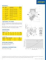
BODY (Seat Hardened) ASTM A743 Gr CA 40 (Cast Equiv. AISI 420) ASTM A743 Gr CA 40 (Cast Equiv. AISI 420) ASTM A743 Gr CA 40 (Cast Equiv. AISI 420) STRAINER SCREEN AISI 304 (Perforated Sheet 0.8) DISC (Hardened) STAINLESS STEEL Blow Down Valve: When the blow down valve is opened, loose material collected in the strainer is purged. ISOTUB: An insulating cover reduces the effect of excessive heat loss resulting from low ambient temperatures, wind, rain, etc. Withdrawal distance for Disc Cap *OPTIONAL FITTINGS DIMENSIONS: PENNANT Flanged Trap MODEL SIZE / RATING Withdrawal distance for Strainer AVAILABLE...
Open the catalog to page 2All Pennant Engineering catalogs and technical brochures
 PT40
PT402 Pages
 CONTROL VALVE
3 Pages
 PISTON VALVE
5 Pages
 Pennant Product Catalogue
8 Pages