- Catalogs
- PEAK Scientific
- Infinity 90 Series
Infinity 90 Series
1 /16Pages

Infinity 90 Series
1 /16Pages
Catalog excerpts
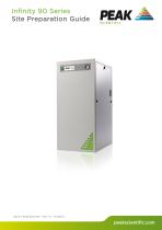
Infinity 90 Series Site Preparation Guide
Open the catalog to page 1
Site Preparation GuideContents Customer Responsibilities 3 Safety Notice to Users 5
Open the catalog to page 2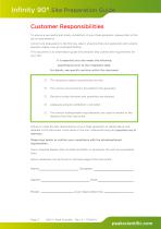
Infinity 90* Site Preparation Guide Customer Responsibilities To ensure a successful and timely installation of your Peak generator, please refer to this set of requirements. Correct site preparation is the first key step in ensuring that your generator and systems operate reliably over an extended lifetime. This document is an information guide and checklist that outlines the requirements for your site. It is essential your site meets the following specification prior to the installation date. For details, see specific sections within this document The necessary spatial requirements are met....
Open the catalog to page 3
Site Preparation Guide Change History
Open the catalog to page 4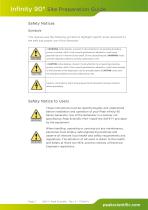
Site Preparation Guide Safety Notices Symbols This manual uses the following symbols to highlight specific areas important to the safe and proper use of the Generator These instructions must be read thoroughly and understood before installation and operation of your Peak Infinity 90 Series Generator. Use of the Generator in a manner not specified by Peak Scientific MAY impair the SAFETY provided by the equipment. When handling, operating or carrying out any maintenance, personnel must employ safe engineering practices and observe all relevant local health and safety requirements and regulations....
Open the catalog to page 5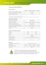
Site Preparation GuideTechnical SpecificationEnvironment * Maximum safety ambient temperature 35°C ** When taken out of storage the Generator should be allowed to acclimatize at room temperature for a minimum of 3 hours before operation. Generator Outlets Electrical Requirements Voltage General Dimensions in cm (inches) W x D x H It should be noted that the gas pressures and flows are factory set. The pressures shown on the Generator front panel are in excess of the maximum inlet pressure of the Mass Spectrometer. This is to allow for known pressure drops.
Open the catalog to page 6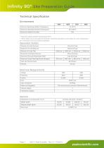
Site Preparation GuideTechnical SpecificationEnvironment * Maximum safety ambient temperature 35°C ** When taken out of storage the Generator should be allowed to acclimatize at room temperature for a minimum of 3 hours before operation. Generator Outlets
Open the catalog to page 7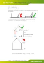
Infinity 90* Site Preparation Guide Site preparation Environmental control The generator must remain on its castors to allow air intake from the bottom of the generator. KEEP CLEAR If the generator is stored in an enclosed space the environment must be controlled via an air conditioner or extraction fan. 30 C Max Relative Humidity; 70% Non-Condensing Generator MUST NOT be stored or installed outside.
Open the catalog to page 8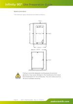
Failing to provide adequate cooling space around the generator may cause damage to the membranes and cause the compressors to run continually. This will reduce service life and invalidate warranty.
Open the catalog to page 9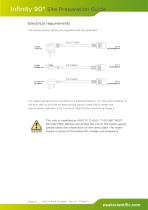
Site Preparation GuideElectrical requirements The below power cables are supplied with the generator. Euro Cable NEMA6-15P IHD II |Ba?P k For cables pertaining to countries not displayed above, it is the responsibility of the end user to provide an appropriate power cable which meets the requirements defined in the Technical Specification section on page 6. This unit is classified as SAFETY CLASS 1. THIS UNIT MUST BE EARTHED. Before connecting the unit to the mains supply, please check the information on the serial plate. The mains supply must be of the stated AC voltage and frequency.
Open the catalog to page 10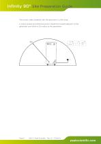
Infinity 90* Site Preparation Guide The power cable supplied with the generator is 2.5m long. A mains socket providing the power should be located adjacent to the generator and within a 2m radius to the generator.
Open the catalog to page 11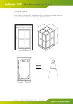
Infinity 90* Site Preparation Guide On-Site Transit When moving the generator in its shipping crate, doorways and other openings such as elevators must fit with the sizes in the figure below.
Open the catalog to page 12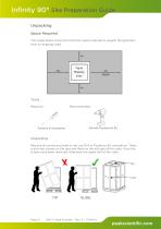
Infinity 90* Site Preparation Guide Unpacking Space Required The image below shows the minimum space required to unpack the generator from its shipping crate. Tools Required : Drill with Pozidrive #2 Bit Unpacking Remove all screws encircled in red, use Drill or Pozidrive #2 screwdriver. There is also two screws on the rear and three on the left side of the crate. Once the screws have been removed, slide back the upper half of the crate.
Open the catalog to page 13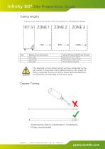
Site Preparation Guide Tubing lengths Tubing sizes should be chosen with accordance to the diagram below. The diameter of the tubing which will be connected to the gas outlet is important and is determined by the length of tubing required. Failure to follow these recommendations could lead to accelerated compressor wear. Copper Tubing
Open the catalog to page 14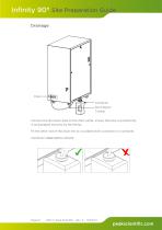
Infinity 90* Site Preparation Guide Drainage Drain Container 6mm Nylon Tubing Connect the 3m Nylon tube to the drain outlet, ensure the tube is pushed fully in and gripped securely by the fitting. Fit the other end of the drain line to a suitable drain connection or container. Containers must not be airtight.
Open the catalog to page 15
Peak Scientific India 202, Amsri Shamira Old Lancer Line Opp. St. Mary's Degree College S.D. Road Secunderabad 500 025, India Tel: +91 40 2780 0663 Fax: +91 40 2780 0663 Peak Scientific Mexico Solon 352 Col. Los Morales Polanco 11530 Mexico, D.F. Mexico Fax: +1 978 608 9503 Peak Scientific Japan K.K. 2-7-56, 2F Fuji Building 28 Kita Aoyama, Minato-Ku Tokyo, Japan 107-0061 Peak Scientific Singapore 3 Science Park Drive #03-14 The Franklin Science Park Drive 1 Singapore, 118223
Open the catalog to page 16All PEAK Scientific catalogs and technical brochures
 Horizen 24
8 Pages
 Precision Air Compressor
2 Pages
 Precision Nitrogen Trace
2 Pages
 Precision Nitrogen
2 Pages
 Infinity XE 60
2 Pages
 Genius XE
8 Pages
 Solaris 10
2 Pages
 Product catalogue
44 Pages
 i-Flow 6XX1
2 Pages
 i-Flow 6XX2
2 Pages
 NM18-45L
12 Pages
 Precision Nitrogen Headspace
2 Pages
 TOC Generators
2 Pages
 Precision single sheet
2 Pages
 GENIUS 1061
2 Pages
 AD140L - AIR DRYER
2 Pages
 AD302L - AIR DRYER
2 Pages


Archived catalogs
 NG Range
2 Pages
 CG15L - 22L
2 Pages
 Precision SL
2 Pages
 SCTOCA
15 Pages
 Infinity 50
2 Pages
 Product catalogue 2017
44 Pages
 ZA015 - ZA300
2 Pages
 Infinity XE 50 Series
2 Pages


- Liebherr air compressor
- Liebherr stationary compressor
- Liebherr industrial compressor
- Liebherr compact compressor
- Liebherr low-noise compressor
- Gas compressor
- Liebherr compressed air dryer
- Liebherr nitrogen generator
- Liebherr PSA nitrogen generator
- Liebherr desiccant compressed air dryer
- Liebherr compact nitrogen generator
- Liebherr laboratory nitrogen generator
- Process nitrogen generator
- Liebherr electric compressor
- Liebherr compact compressed air dryer
- Liebherr pure nitrogen generator
- Liebherr hydrogen generator
- Service compressor
- Liebherr laboratory compressor