- Catalogs
- PDM Analysis Ltd
- SCORGTM Setup for CFD Simulation of Twin Screw Machines with ANSYS CFX®
SCORGTM Setup for CFD Simulation of Twin Screw Machines with ANSYS CFX®
1 /35Pages

SCORGTM Setup for CFD Simulation of Twin Screw Machines with ANSYS CFX®
1 /35Pages
Catalog excerpts

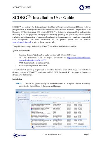
SCORGTM Setup for CFD Simulation of Twin Screw Machines with ANSYS CFX® SCORGTM is the CFD grid generation tool for rotary twin screw machines. The tool includes additional modules for designing and editing rotor profiles, executing a basic thermodynamic calculation based on quasi 1D chamber models and generating the deforming working chamber grids for selected commercial CFD solvers. For more information on the product please visit the website: www.pdmanalysis.co.uk or refer to documentation help. This guide lists the steps for setting up a CFD simulation for Twin Screw Compressor with SCORGTM and ANSYS CFX Solver. The user is expected to be familiar with screw machines, CFD and ANSYS CFX® in order to be able to use these procedures. It is highly recommended that books on that topic are studied12 The setup steps here are demonstrated for Linux & Windows 7, x64 bit OS. Refer SCORGTM Installation Guide for system and hardware requirements. N. Stosic, I.K. Smith, A. Kovacevic Screw Compressor Mathematical Modelling and Performance Calculation, Springer, UK 2005, ISBN-10 3-540-24275-9 2 A. Kovacevic. N. Stosic, I.K. Smith, Screw Compressor Three Dimensional Computational Fluid Dynamics and Fluid Solid Interaction, Springer, 2006, ISBN 3-540-36302-5
Open the catalog to page 1
1 Introduction Screw Compressors are rotary positive displacement machines. Although the working principle of these machines is simple, the geometry of rotors which are in the form of multi -lobe helical screws meshing with each other, is making analysis by use of Computational Fluid Dynamics (CFD) challenging. The process starts when the lobes are engaged at one end, which creates continuous increase of the volume between the rotors and the casing which reduces pressure in the suction domain and draws the working fluid in. Further rotation of the rotors makes this volume between the rotors and...
Open the catalog to page 2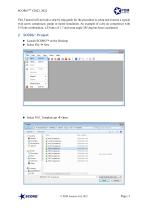
SCORGTM V2022, 2022 This Tutorial will provide a step by step guide for the procedure to setup and execute a typical twin screw compressor, pump or motor simulation. An example of a dry air compressor with 3/5 lobe combination, L/D ratio of 1.7 and wrap angle 285 deg has been considered. 2 SCORGTM Project Launch SCORGTM on the Desktop. Select File → New
Open the catalog to page 3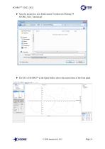
SCORGTM V2022, 2022 Save the project in a new folder named TwinScrewCFXSetup → SCORG_Grid_Tutorial.spf The GUI of SCORGTM in the figure bellow shows the mains items of the front panel.
Open the catalog to page 4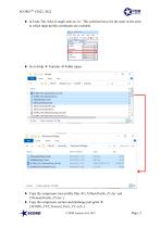
SCORGTM V2022, 2022 In Units Tab, Select Length units as ‘m’. This selection has to be the same as the units in which input profile coordinates are available. Go to Help → Tutorials → Folder opens Copy the compressor rotor profile files → [ 35MaleProfile_P1.dat and 35FemaleProfile_P2.dat ] Copy the compressor suction and discharge port grids → [ SCORG_CFX_Tutorial_Ports_V5.4.cfx ] © PDM Analysis Ltd, 2022
Open the catalog to page 5
SCORGTM V2022, 2022 Copy the CFX setup script → [ SCORG_CFX_Tutorial_V5.9.ccl ] Paste these files in the working directory → TwinScrewCFXSetup Go to User Profile → Browse and Select the Male Rotor Profile from working directory. 35MaleProfile_P1.dat Similarly Select the Female Rotor Profile. 35FemaleProfile_P2.dat Click Write To Default.
Open the catalog to page 6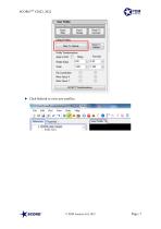
Click Refresh to view new profiles.
Open the catalog to page 7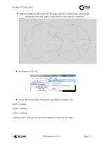
SCORGTM V2022, 2022 Inspect the Rotor Profile in the GUI for gaps in the tips, starting points of the profile indicated by the small yellow circles. Below is the required orientation. Set the following Profile Parameters to get desired clearance size: GAPI = 0.06mm GAPR = 0.06mm GAPA = 0.05mm *Setting GAPI = 0.06 sets the minimum interlobe clearance as the GAPI.
Open the catalog to page 8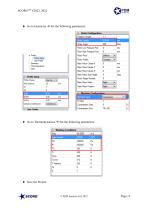
Go to Geometry → Set the following parameters: Go to Thermodynamics → Set the following parameters:
Open the catalog to page 9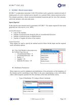
3 SCORGTM Mesh Generation SCORGTM is stand-alone numerical CAD-CFD interface used to generate a numerical mesh of rotating parts of a screw machine and to transfer it to a general finite volume numerical solver. The program generates a block structured hexahedral numerical grid for rotor flow domains, solid rotor domains, inlet and outlet ports. Inputs Required In this step the rotor domain mesh is generated in SCORGTM. The inputs required for this mesh generation are: (Kovacevic, et al., 2007). Control Parameters: • Type of the machine. • Number of mesh divisions along the lobe in circumferential...
Open the catalog to page 10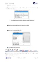
SCORGTM V2022, 2022 Meshing Parameters: Meshing parameters provide control over the distribution of the internal mesh points in each cross section of the rotors. o both the distribution and meshing parameters can be changed later Start Grid Generation through a three step process as below. Select Rack Refinement Points = 400 Click Numerical Rack Generation This operation produces the rack curve between the two profiles. It is required to be executed only once in the grid generation process.
Open the catalog to page 11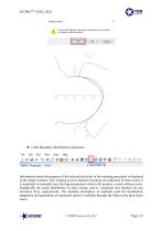
Click Boundary Distribution Generation Information about the progress of the selected activities in the meshing procedure is displayed in the output window. Any warning or error and their locations are indicated. If errors occur, it is important to manually tune the input parameters which will produce a mesh without errors. Graphically the mesh distribution in each section can be visualized and checked for any deviation from requirements. The detailed description of methods used for distribution, adaptation and generation of numerical mesh is available through the Help in the drop down menu.
Open the catalog to page 12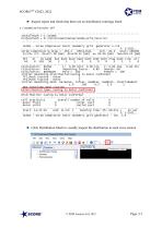
SCORGTM V2022, 2022 Inspect report and check that there are no distribution warnings listed Click Distribution Mesh to visually inspect the distribution in each cross section
Open the catalog to page 13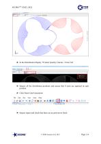
In the Distribution Display → Select Quality Criteria = Error Cell Inspect all the distribution positions and ensure that 0 error are reported in each position. Click Rotor Grid Generation Inspect report and check that there are no grid errors listed
Open the catalog to page 14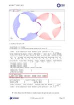
Click Rotor Grid 2D Mesh to visually inspect the grid in each cross section
Open the catalog to page 15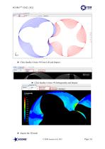
Click Quality Critera → Error Cell and Inspect. Click Quality Critera → Orthogonality and Inspect. Inspect the 3D mesh © PDM Analysis Ltd, 2022
Open the catalog to page 16