- Catalogs
- PDM Analysis Ltd
- SCORG TM Setup for Analysis of Twin Screw Machines with Design Exploration
SCORG TM Setup for Analysis of Twin Screw Machines with Design Exploration
1 /27Pages

SCORG TM Setup for Analysis of Twin Screw Machines with Design Exploration
1 /27Pages
Catalog excerpts

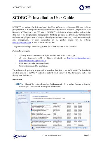
SCORGTM Setup for Analysis of Twin Screw Machines with Design Exploration SCORGTM is the unique design platform for rotary twin screw machines. The tool includes additional modules for designing and editing rotor profiles, executing a basic thermodynamic calculation based on quasi 1D chamber models and generating the deforming working chamber grids for selected commercial CFD solvers. For more information on the product please visit the website: www.pdmanalysis.co.uk or refer to documentation help. This guide lists the steps for setting to use Design Exploration Framework with SCORGTM. The user is expected to be familiar with screw machines, CFD and SCORG Thermodynamic model in order to be able to use these procedures. It is highly recommended that books on that topic are studied 12 1 Introduction During the design of twin screw compressors and expanders, it is required to vary several geometrical and operational variables to achieve best performance for a given operating condition. SCORG has been used for this purpose by setting the initial configuration of the rotors, clearance sizes and then calculating the performance. When design variable is changed, a new project is setup and performance recalculated. All the data collected by this means can N. Stosic, I.K. Smith, A. Kovacevic Screw Compressor Mathematical Modelling and Performance Calculation, Springer, UK 2005, ISBN-10 3-540-24275-9 2 A. Kovacevic. N. Stosic, I.K. Smith, Screw Compressor Three Dimensional Computational Fluid Dynamics and Fluid Solid Interaction, Springer, 2006, ISBN 3-540-36302-5
Open the catalog to page 1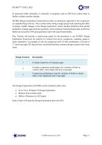
SCORGTM V2022, 2022 be processed either internally or externally in programs such as MS-Excel which helps to further evaluate machine designs. SCORG Design Exploration Framework provides an automation approach in the compressor or expander design activity. This is achieved by setting a single project and exploring the effect of design variable changes in the Design Exploration. Entire machine definition from profile parameters, leakage gaps and rotor geometry can be explored. Selected design data can then be further processed for CFD grid generation and CAD export functionality. This Tutorial...
Open the catalog to page 2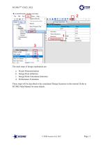
The main steps of design exploration are: a. b. c. d. Project Parameterisation Design Point definition Design Point Calculation Selection Performance Evaluation These steps will be described in the considered Design Scenarios in this tutorial. Refer to SCORG Help Manual for more details.
Open the catalog to page 3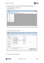
2 Design Scenario 1: Evaluate sensitivity of clearance gaps Launch SCORGTM on the Desktop. Select File New Save the project in a new folder
Open the catalog to page 4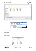
Set the following Profile Parameters to get desired clearance size: GAPI = 0.06mm GAPR = 0.06mm GAPA = 0.05mm Go to Thermodynamics Set the following parameters: © PDM Analysis Ltd, 2022
Open the catalog to page 5
Save the Project. Run Geometry and Thermodynamics Inspect the performance data
Open the catalog to page 6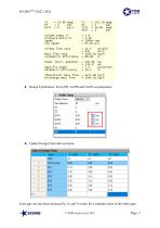
Design Exploration: Set GAPI, GAPR and GAPA as parameters Update Design Point data as below Each gap size has been increased by 2x and 3x times for a constant value of the other gaps. © PDM Analysis Ltd, 2022
Open the catalog to page 7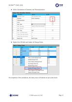
SCORGTM V2022, 2022 Select Calculations of Geometry and Thermodynamics Right-Click DP table and Update All Design Points On completion of the calculations, the status icons will indicate an up-to-date result.
Open the catalog to page 8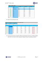
Review the performance data It can be seen from the volumetric efficiency data that the sensitivity of GAPI is highest and GAPA is the least for this compressor design at the given operating condition.
Open the catalog to page 9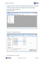
3 Design Scenario 2: Evaluate compressor performance for variation of built-in volume index, rotor length and rotor wrap angle Launch SCORGTM on the Desktop. Select File New Save the project in a new folder © PDM Analysis Ltd, 2022
Open the catalog to page 10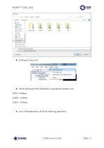
Set the following Profile Parameters to get desired clearance size: GAPI = 0.06mm GAPR = 0.06mm GAPA = 0.05mm Go to Thermodynamics Set the following parameters:
Open the catalog to page 11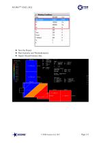
Save the Project. Run Geometry and Thermodynamics Inspect the performance data
Open the catalog to page 12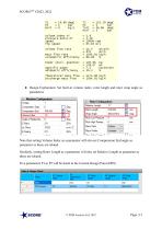
Design Exploration: Set built-in volume index, rotor length and rotor wrap angle as parameters Note that setting Volume Index as a parameter will also set Compression End angle as parameter as these are related. Similarly, setting Rotor Length as a parameter will also set Relative Length as parameter as these are related. Five parameters P1 to P5 will be listed in the Current Design Point (DP0)
Open the catalog to page 13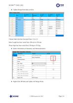
SCORGTM V2022, 2022 Update Design Point data as below Volume Index has been increased from 1.2 to 2.2. Rotor Length has been varied from 180 mm to 250 mm. Wrap Angle has been varied from 250 deg to 325 deg. Select Calculations of Geometry and Thermodynamics Right-Click DP table and Update All Design Points
Open the catalog to page 14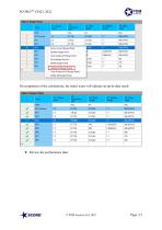
On completion of the calculations, the status icons will indicate an up-to-date result. Review the performance data
Open the catalog to page 15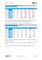
It can be seen from the volumetric efficiency data that the sensitivity of GAPI is highest and GAPA is the least for this compressor design at the given operating condition. Click on the Specific Power column title to arrange data in ascending order. Lest Specific Power is obtained for DP3 with Volume Index = 2.2 as the compressor discharge pressure is set at 3.0 bar. For short rotors of DP4 = 180 mm with low Volume Index = 1.2, the Specific Power is the highest. Click on the Volumetric Efficiency column title to arrange data in descending order.
Open the catalog to page 16
Highest Volumetric Efficiency is obtained again for DP3.
Open the catalog to page 17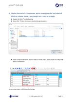
4 Design Scenario 3: Compressor performance map for variation of built-in volume index, rotor length and rotor wrap angle Launch SCORGTM on the Desktop. Select File Open the project saved in Design Scenario 2 Open Design Exploration: Set for built-in volume index, rotor length and rotor wrap angle as parameters An up-to-date status will be seen for the data.
Open the catalog to page 18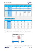
Design Exploration: Set Rotor Speed and Discharge Pressure for performance map. In Thermodynamics Working Conditions, set Rotor Speed and Discharge Pressure In Thermodynamics Thermodynamic Controls, set Speed loop, Discharge Pressure loop, Tip speed increment and Discharge Pressure increment values. © PDM Analysis Ltd, 2022
Open the catalog to page 19