
- Catalogs
- PBP Optel sp. z o.o.
- OPBOX ver 2.1

- Products
- Catalogs
- News & Trends
- Exhibitions
OPBOX ver 2.1
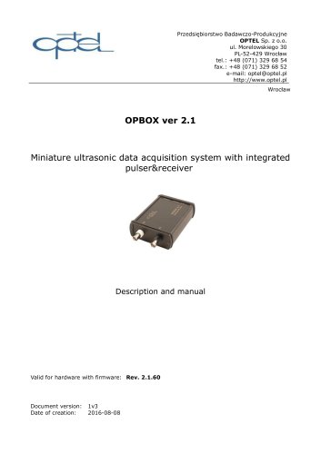
OPBOX ver 2.1
The OPBOX ver 2.1 is a compact ultrasonic data acquisition system featuring an adjustable amplifier range from -31dB to 65dB, a switchable preamplifier of +24dB, and a bandwidth of 0.5 MHz to 25 MHz. The pulser voltage is adjustable from 0V to 360V, and the A/D converter has a 10-bit resolution with a maximum input voltage of ±0.5V. It supports a sampling frequency range from 6.67 MHz to 100 MHz and includes a 256k sample FIFO buffer.
The device is controlled via USB-2.0 using direct commands and control registers. Key commands include OPBOX_SN, RESET, and PULSE_AMPLITUDE. Control registers manage functions such as power control, packet length, and trigger settings.
The OPBOX-2.1 is USB-powered and requires enabling power supply branches before operation. It includes mechanisms to check power status and handle power supply issues, blocking measurement commands if a failure is detected.
The system supports real-time acquisition speeds of up to 10,000 measurements per second. Data is stored in internal memory and can be read in packets, allowing for high-speed measurements. FIFO mode supports real-time acquisition without immediate data reading.
Key elements include:
- Acquisition: A single measuring sequence with settings for sampling frequency, delay time, and measurement window size.
- Measurement Window: Adjustable from 1 to 262090 samples.
- StoreDisabled: Stores only the acquisition header to increase speed.
- Header: A 54-byte section containing acquisition information.
- Frame: Consists of a header and measurement data.
- Packet: A collection of acquisitions stored until the PACKET_READY flag is set.
- Real-Time Acquisition: Continuous acquisitions triggered by external signals.
The document outlines data organization in acquisition systems, focusing on header and packet configurations. The header size is fixed at 54 bytes, while frame size is determined by adding header size to data depth.
The acquisition header is detailed byte by byte, with specific functions and values assigned to each byte, crucial for managing and interpreting acquisition data.
Provides a guide for configuring and maintaining acquisition in real-time, ensuring the device is ready for data acquisition and can handle data efficiently.
Involves checking packet readiness and managing the buffer to ensure data integrity, including procedures for reading remaining frames and resetting the memory controller.
Discusses the calculation of maximal packet length based on hardware buffer capacity and measurement window depth, highlighting the importance of optimizing settings for efficient data transfer.
Outlines conditions that can block acquisition triggering, such as ongoing acquisitions and full buffer memory, to prevent data loss and ensure system stability.
The POWER_CTRL register monitors power supply status flags. Errors during trigger events halt acquisition, incrementing the TrgOverrun counter and setting the TrgOvrScr_P bit in the CAPT_REG for diagnostics.
The acquisition buffer can be reset using the DIRECT_RESET_FIFO command, clearing all acquisitions without altering settings.
Configuring TGC curves in FIFO mode requires a prepared table matching the buffer size, with specific byte arrangements to prevent acquisition errors.
Includes three peak and level detector modules with configurable gates and modes, storing results in the acquisition header and resetting after each acquisition.
Supports two encoder modules for incremental encoders with quadrature inputs, featuring a 32-bit position counter and configurable work modes.
Catalog excerpts
Przedsi^biorstwo Badawczo-Produkcyjne OPTEL Sp. z o.o. ul. Morelowskiego 30 PL-52-429 Wroclaw tel.: +48 (071) 329 68 54 fax.: +48 (071) 329 68 52 e-mail: [email protected] http://www.optel.pl Valid for hardware with firmware: Rev. 2.1.60 Document version: 1v3 Date of creation: 2016-08-08
Open the catalog to page 1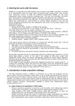
3. Starting the work with the device OPBOX-2.1 is powered from USB interface and is conform with USB2.0 standard. According to its requirements there are some limits, concerning power supply (max. start current, max. continuous power). To fulfill this standard requirements OPBOX 2.1 has three independent power supply branches (analogue part, 12V part and ADC/DAC converters part). Each branch has independent signals, switching it and showing error conditions. After connecting the device to the USB port, all three branches are switched off and only digital part, responsible for communication is...
Open the catalog to page 6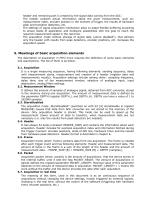
header and remaining part is created by the signal data coming from the ADC; The header contains actual information about the given measurement, such as: measurement index, encoder position in the moment of trigger, the results of hardware peak and transition detectors, etc. The settings of signal acquisition mechanism allow to adapt flexible buffering according to actual needs of application and hardware possibilities with the goal to reach the required measurement speed in the real time. The acquisition mode without storage of signal data („store disabled“), that delivers only the header with...
Open the catalog to page 7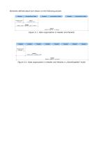
Elements defined above are shown on the following picture. Figure 5.1: Data organization in Header and Packets Header
Open the catalog to page 8
7. Configuration and maintenance of acquisition in real time Configuration and maintenance of acquisition in real time should be made according to the following schematic: 1. Stop of acquisition, that is going on: blocking all trigger sources (bit TriggerEnable in TRIGGER register). 2. Setting of acquisition parameters: - Sender configuration - loading time and voltage level (register PULSE_TIME and PULSE_AMPLITUDE); - Analogue channel configuration - choice of input, attenuator, low and high pass filters, amplification (register ANALOG_CTRL, MEASURE, CONST_GAIN); - configuration of signal acquisition...
Open the catalog to page 10
- receiving all packets until the moment as the flag PACKET_READY will have zero value. - the device buffer can contain a fragmentary acquisition packet (not the whole PACKET_LEN), the amount of remaining frames should be read from the register FRAME_CNT; - if FRAME_CNT = 0 it means, that all frames was received and the reading was correctly finished. - if FRAME_CNT is not equal zero (i.e N) the setting PACKET_LEN should be changed to exactly the amount of frames, that is remaining in the buffer of the device (N should be written to the register PACKET_LEN). Only in this situation the change...
Open the catalog to page 11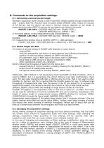
8. Comments to the acquisition settings. 8.1. Calculating maximal packet length Hardware acquisition buffer allows to store maximally 256kB samples (single measurement data – exactly 262144). Maximal value of packet length (PACKET_LEN), means the amount of full frames, that the device can store in internal memory depends on the length of measurement window (DEPTH) and can be calculated from following formulas: PACKET_LEN_MAX = INTEGER PART[262144 / FRAME_SIZE] = = INTEGER PART[262144 / (DEPTH + 54)] In the mode without writing measurement data (StoreDisabled): PACKET_LEN_MAX = INTEGER PART[262144...
Open the catalog to page 12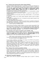
8.3.1. Change of the measurement window setting (DEPTH) Changing of DEPTH setting causes that it is necessary to calculate new parameters of acquisition buffering (PACKET_LEN_MAX, placing of frames in relation to memory of TGC curve, etc.). Changing DEPTH parameter automatically changes the packet length too. For this reason each change of the length of measurement window (writing to DEPTH register) causes the reset of acquisition buffer. All acquisitions that are stored in the buffer are removed. To avoid the loss of data stored in the acquisition buffer it is recommended to change the DEPTH...
Open the catalog to page 13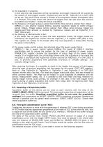
a) the acquisition in progress In this case the new acquisition will be not started, and trigger impulse will be counted by the module of lost triggers counter (TrgOverrun) and the bit TrgOvrScr_A in CAPT_REG will be set. The value of this counter is written to the acquisition header immediately after it is finished. This value shows the amount of triggers that was lost since the previous acquisition was finished – during the actual acquisition. b) the frequency of trigger pulses is larger than 10kHz (their period is smaller than 100µs) OPBOX-2.1 has internal module limiting maximal repetition...
Open the catalog to page 14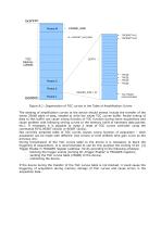
Frame 3 Frame 2 HEADER_SIZE = 54 Figure 8.1: Organization of TGC curves in the Table of Amplification Curves The sending of amplification curves to the device should always include the transfer of the whole 256kB table of data, needed to write the whole TGC curves buffer. Partial writing of data to this buffer can cause wrong function of TGC function during some acquisitions and cause problem with following writing curves to the memory (shift of hardware data pointer, etc.). If necessary it is possible to make a reset of TGC curves controller using the commands FIFO_RESET (0xD2) or RESET (0xD1)....
Open the catalog to page 15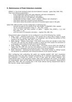
9. Maintenance of Peak Detectors modules OPBOX 2.1 has three hardware peak and level detector modules – gates PDA, PDB i PDC. They have following parameters: – three independent gates with peak detectors and level comparators; – configurable start and stop point for each gate; – configurable level for level detector (comparator); – configurable function modes: „Level”, „Rising”, „Falling” and „Transition”; – information about the moment of level transition; – information about the position and level of maximal signal value in the gate. Gates PDA, PDB and PDC must be configured in a following...
Open the catalog to page 16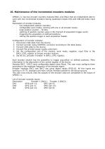
OPBOX 2.1 has two encoder counters modules ENC1 and ENC2 that are independent able to work with two incremental encoders having quadrature inputs CHA and CHB and index input IDX. Parameters of encoder modules: - two independent position counters; - configurable work modes, working with one or all encoder inputs; - large position counter - 32-bits; - catching of position counter value in the moment of acquisition trigger event; - triggering the acquisition on defined positions; - storing the position trigger in each acquisition header. Configuration of encoder modules: 1. Disconnect USB cable...
Open the catalog to page 17All PBP Optel sp. z o.o. catalogs and technical brochures
 OPTIM 2.0
2 Pages
 OPCARD 3.0
2 Pages
 OPBOX ver 2.2
17 Pages
 OPCARD 3.0
2 Pages
 OPGS BURST GENERATOR
1 Page
 OPLabBox
1 Page
 OPCARD 2.0
2 Pages
 OPGUD
6 Pages


- Measuring device
- Welder
- Generator
- Transceiver module
- Portable gauge
- Industrial measuring module
- Ultrasonic transducer
- Single-phase welder
- 3D scanning system
- Measurement scanner
- Automatic measuring module
- Inspection scanner
- Welding power supply
- Laboratory measuring instrument
- Radio transceiver module
- Flaw detector
- Pulse generator
- Piezoelectric ultrasonic transducer
- Welder with integrated display
- Multiplexer